


10 - 2
10
e-STUDIO350/352/353/450/452/453
DRIVE SYSTEM
© 2003 - 2008 TOSHIBA TEC CORPORATION All rights reserved
(MAMCK)
MAMPL
MAMCW
MAMBK
MAMON
Wave
correction
Phase
comparator
Speed
comparator
Lock
protection
circuit
Rotor
position
detection
Voltage
detection
circuit
Rotation
control
Excitation
phase
switching
section
Main motor (PC board)
Main motor (Motor)LGC board
24v
Phase W
Phase V
Phase U
Hall element C
Photo-
interuptor
FG pulse
Hall element A
Hall element B
CN318
24v
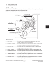
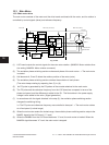
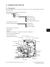
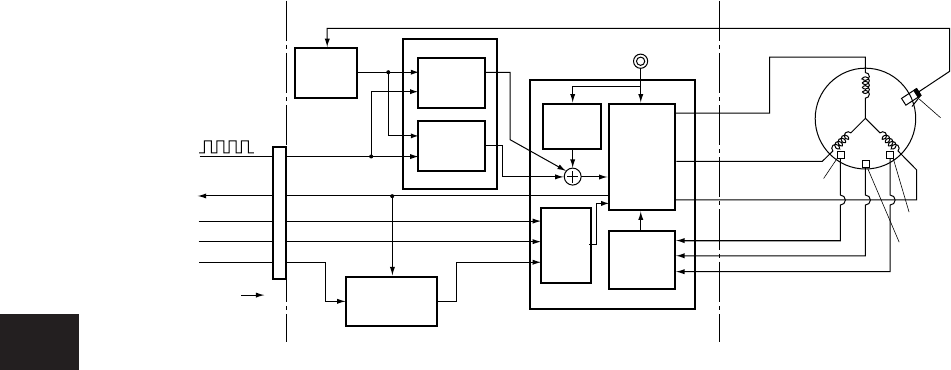
10.3 Main Motor
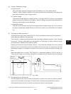
10.3.1 Main motor drive
The main motor consists of the motor and the drive board combined with the motor, and its rotation is
controlled by control signals (three) and reference frequency.
(1) LGC board outputs the control signals for the main motor rotation. (MAMCW: Motor rotation direc
-
tion setting, MAMON: Motor rotation command)
(2) The excitation phase switching section excites each phase of the main motor.
→
The main motor
is rotated.
(3) Hall elements A, B and C detect the rotation position of the motor (rotor).
(4) The excitation phase switching section switches the excitation of each phase.
(The motor keeps rotating by repeating from (2) to (4).)
(5) An FG pulse is generated by the FG pattern of the encoder attached to the main motor.
(6) The FG pulse and the reference frequency from the LGC board are compared in terms of the
phaseandspeed,andthedifferenceisaddedtotheIC1.Theuctuationsinthepowersupply
voltage is also added to the value. (Signal generation)
(7) In accordance with the signal obtained in the step (6), the excitation phase switching section
changes the switching timing.
i.e. The FG pulse and reference frequency are controlled to be equal.
→
The main motor rotates
ataxedspeed.(Lockedrange)
(8) When the main motor enters the locked range, the excitation phase switching section outputs the
MAMPL signal to the LGC board. (“L” level)
(9) When the MAMBK from the LGC board becomes “L” level, the main motor is braked. When the
MAMON signal becomes “H” level, the main motor is stopped.
Fig. 10-301