


UPS Connections
Standard Unit with 120V Isolation Module
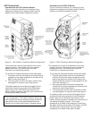
Figure 2 shows the standard unit, consisting of one
electronics module and one battery module, with the
addition of the 120V isolation transformer module.
The modules do not have to be stacked for the unit to
operate; however, if the modules are to be stacked
please refer to the 1700 Series user manual for
instructions on interlocking modules.
To connect the modules electrically follow these steps:
1. The power cord from the electronics module must be
plugged into the output receptacle on the back of the
option module (see figure 1).
2. The input power cord from the option module must
be plugged into a power source (see figure 1).
The battery power cord must also be plugged into the
electronics module for the system to provide backup
power (refer to the 1700 Series user manual or the
battery module installation instructions for instructions on
connecting the battery module).
Note: No more than three modules should be stacked
in any configuration. If the option module is being used
with a system that has an expansion battery module at
least one module must be placed beside the others.
Stacking four modules could result in a tipping hazard.
Standard Unit with 230V IO Module
Figure 3 shows the standard unit, consisting of one
electronics module and one battery module, with the
addition on the 230V transformer module.
The modules do not have to be stacked for the unit to
operate; however, if the modules are to be stacked
please refer to the 1700 Series user manual for
instructions on interlocking modules.
To connect the modules electrically follow these steps:
1. Plug the output power cord from the transformer
module into one of the output receptacles on the
back of the electronics module (in the case of the
2.4kVA model the cord can only be plugged into the
20A outlet, see figure 1).
2. Next, plug the power cord from the electronics
module into the output receptacle on the back of the
transformer module (see figure 1).
3. The input power cord from the transformer module
must be plugged into a power source (see figure 1).
The battery power cord must also be plugged into the
electronics module for the system to provide backup
power (refer to the 1700 Series user manual or the
battery module installation instructions for instructions on
connecting the battery module). The unused
receptacles on the back of the electronics module are
still active, but they are providing 120V power, not 230V.
All 230V power must be drawn from the output
receptacles on the back of the option module.
Figure 2 : 120V Isolation Transformer Module Configuration Figure 3: 230V Transformer Module Configuration