


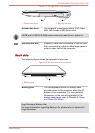
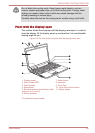
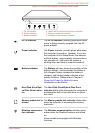
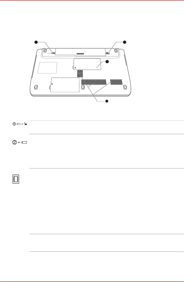
Underside
The following figure shows the underside of the computer. You should
ensure that the display is closed before the computer is turned over to
avoid causing any damage.
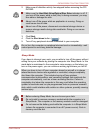
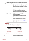
Figure 2-5 The underside of the computer
1 2
3
4
1. Battery lock 3. Memory module slot
2. Battery release latch 4. Cooling vents
Battery lock Slide the battery lock to release the battery pack
ready for removal.
Battery release latch Slide and hold this latch into its "Unlock" position
in order to release the battery pack for removal.
For more detailed information on removing the
battery pack please refer to Chapter 5, Power
and Power-Up Modes.
Memory module slot The memory module slot allows for the
installation, replacement and removal of
additional memory modules.
1 GB, 2 GB or 4 GB memory modules can be
installed in the computer's two memory slots for a
maximum of 8 GB system memory. The actual
amount of useable system memory will be less
than the installed memory modules.
Refer to the Additional memory module section in
Chapter 3, Operating Basics.
Cooling vents The cooling vents help the processor avoid
overheating.
C670/C670D/L770/L775/L770D/L775D
User's Manual 2-5