


G9 Drive
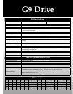
G9 Specications
Model Range 1 to 150 HP 1 to 350 HP
Voltage Rating 200 to 240 V 380 to 480 V
Input Voltage Tolerance
±10% ±10%
Voltage Regulation Main Circuit Voltage Feedback Control (Automatic Regulation, ‘Fixed’ and ‘Control Off’ Selections)
PWM Carrier Frequency
Adjustable 0.5 to 15 kHz (ASD Specic, Consult Factory)
Control System
Sine Wave PWM System - Flux eld current vector control
V/f Pattern
Open Loop Vector, Closed Loop Vector, Constant Torque, Variable Torque, Auto Torque Boost, Manual Torque Boost,
5-Point V/f Custom Curve Setting
Overload Current Rating 115% Continuous, 150% for Two Minutes up to 100 HP, Consult Factory for Ratings Above 100 HP
Frequency Setting
Rotary Encoder Integrated into EOI, 0 to 10 V,
±10 V, 4 to 20 mA, Binary Input, Motorized Potentiometer Input
Frequency Precision
Analog Input
±0.2% of the Maximum Output Frequency, Digital Input ±0.01% of the Maximum Output Frequency
Output Frequency Range 0 to 299 Hz
Speed Regulation Closed Loop (Up to 0.01%, 1000:1 Speed Range), Open Loop (Up to 0.1%, 60:1 Speed Range)
Discrete Input Terminals
Eight Discrete Input Terminals Programmable to 67 Functions; Number of Terminals may be Increased Using Optional
Hardware
Analog Inputs
One 4 to 20 mA, One 0 to 10 V, and One
±10 V
Discrete Output Contacts Three Output Contacts Programmable to 127 Functions
Analog Outputs One Programmable 4 to 20 mA or 0 to 10 V and One 4 to 20 mA Output
Control Board Communication Ports 2-Wire/4-Wire RS485
Power Terminals Input (L1, L2, L3); Output (T1, T2, T3); DCL(PO,PA); DBR (PA,PB); DC BUS (PA, PC)
PID (Set Point Control)
Proportional Gain, Integral Gain, Feedback Settings Upper/Lower Deviation Limits, Feedback Source Delay Filter,
Feedback Settings Differential Gain
Retry ASD can clear some faults upon trip automatically.
Restart ASD will catch a coasting motor smoothly.
Ambient
Operating Temperature: -10 to +40
°C; 14 to 104°F Humidity: 95% Non-Condensing
Installation NEMA 1 Enclosure Type
Electronic Operation Interface (EOI)
LCD EOI (Liquid Crystal Display/
Electronic Operator Interface)
Full English Back-Lit Display
LED EOI Light Emitting Diode; Seven Segment Display
LED Indicators Run (Red)/Stop (Green), Local/Remote (Green), DC Bus Charge Indicator (Red)
Keys Local/Remote, ESC, Run, Mode, Stop/Reset
Rotary Encoder Encoder with Integrated Enter Key for Frequency and Parameter Adjustments
Monitoring
Main Display Shows Two Monitored Items or can Display up to 17 User-Selected Scrolling Items Including: Output
Frequency, Output Current, Output Voltage, Input Power, Output Power, Motor Overload Ratio, DC Bus Voltage,
Compensation Frequency, PID Feedback, AM Output, FM Output, Motor Load, ASD Load, Run Time
Selectable Display Units
Completely Congurable along with Scaling Factor Multiple; Current Display Selectable Between Amps or %; Voltage
Display Selectable Between Volts or %
EOI Communications Ports RS232/485 ports standard
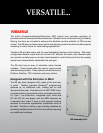
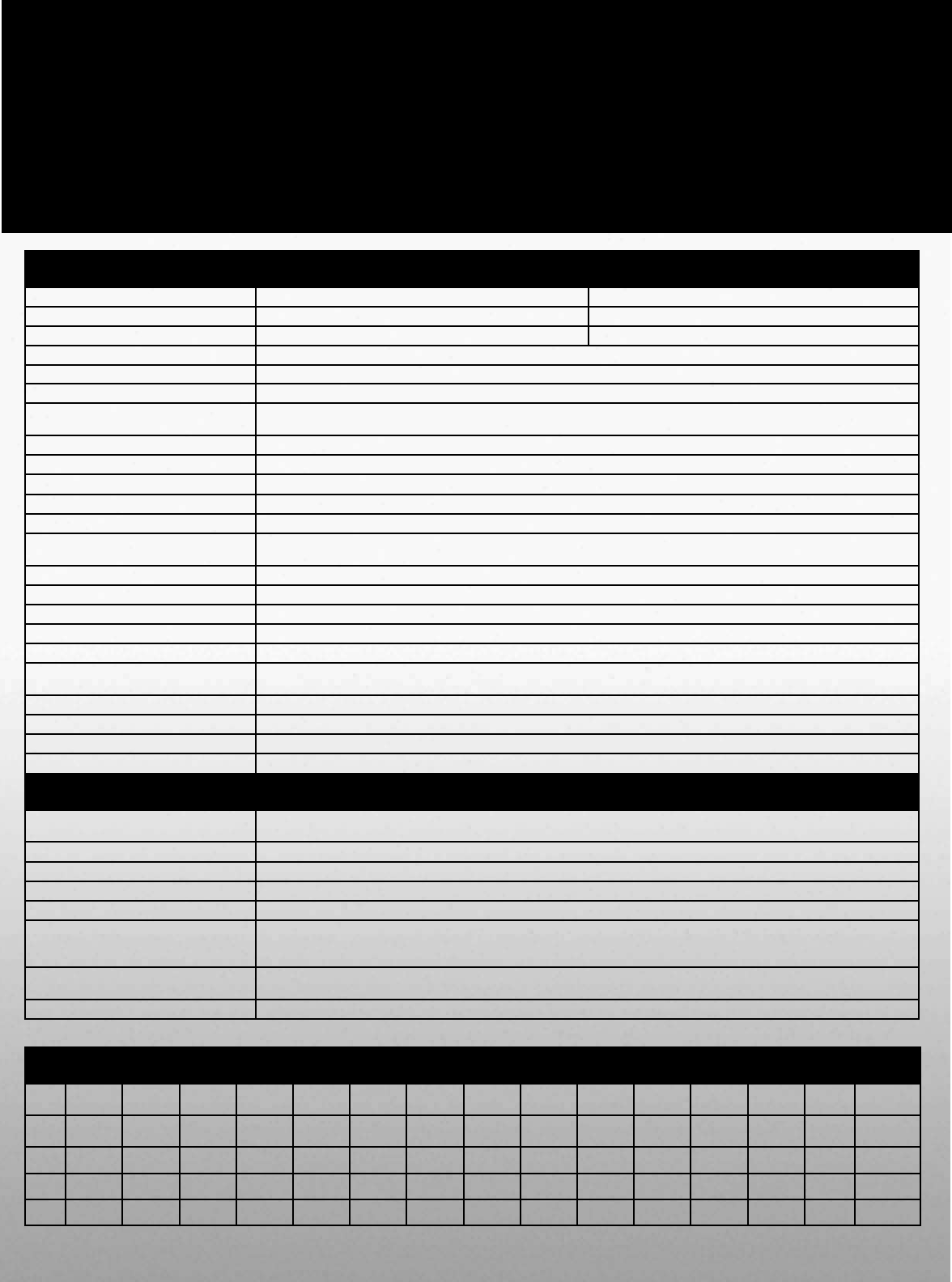
G9 Dimensions
230 V 0.75 to 2 HP 3 to 5 HP 7.5 HP 10 HP 15 to 20 HP 25 to 30 HP NA 40 to 60 HP NA 75 HP 100 HP NA NA NA NA
460 V 1 to 3 HP 5 HP 7.5 to 10 HP 15 HP 20 to 25 HP 30 HP 40 to 50 HP
NA 60 to 100 HP 125 HP NA 150 HP 200 HP 250 HP 300 to 350 HP
Height
(in.)
11.2 12.4 15 15.1 19.3 25.9 30.8 33.1 36.1 51.7 53.1 53.2 63.1 68.5 70
Width
(in.)
5.2 6.1 6.9 8.3 9.1 11.1 11.1 14.3 14.3 14.6 14.8 15.7 15 18.9 25.6
Depth
(in.)
6.1 6.6 6.6 7.6 7.6 13.2 14.3 15 15.3 17.6 17.6 17.6 17.6 17.6 17.6