


Meets or Exceeds
Your Specications
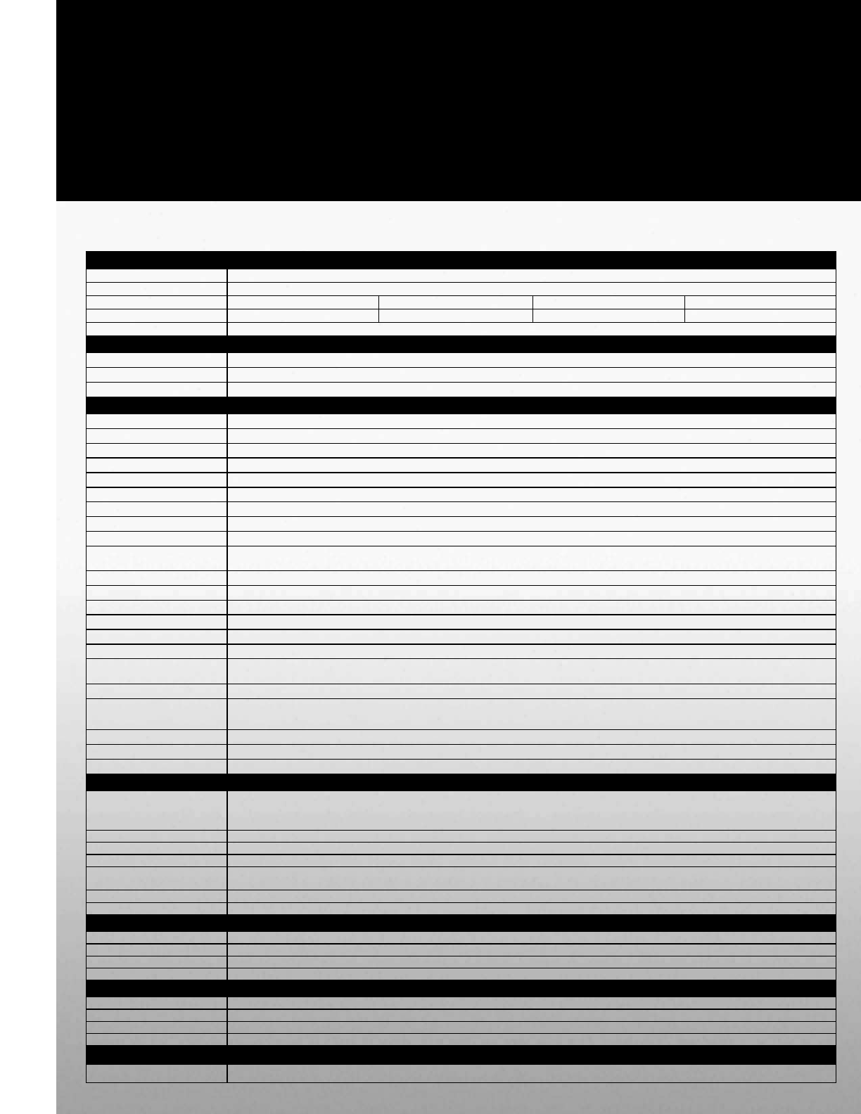
GX7 Specications
Standard Specications
Item
Voltage Class 600 VAC
Maximum HP 500 HP 600 HP 700 HP 800 HP
Drive Rating (A) 481 A 601 A 698 A 770 A
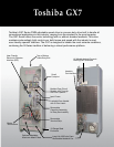
Dimensions 95”H x 32”W x 30.5”D
Power Requirements
Output Frequency 0 to 299 Hz
Control Power DC Bus Control Power
Tolerance Voltage: ±10%; Frequency: ±2%
Control Specications
Control Method Sine Wave PWM System; Flux Field Current Vector Control
V/Hz Control Constant Torque, Variable Torque, Open-Loop Vector, Auto or Manual Torque Boost, 5-Point V/Hz Custom Curves
Overload Rating 130% for 120 Seconds; 110% Continuous
Frequency Setting Rotary Encoder Integrated into EOI, 0 to 10 V, ±10 V, 4 to 20 mA, Binary Input, Motorized Potentiometer Input
Frequency Precision Analog Input: ±0.2% of Maximum Output Frequency; Digital Input: ±0.01% of Maximum Output Frequency
Frequency Resolution Panel Operation: 0.01 Hz; Analog Input 10 to 12-Bit A to D Converter: 0.1 Hz
Acceleration / Deceleration 0.1 to 6000 Seconds
Speed Regulation Up to 0.1%; 60:1 Speed Range
Torque Setting ±250% of the Rated Torque
Set Point Control (PID)
Proportional Gain, Integral Gain, Feedback Settings Upper/Lower Deviation Limits, Feedback Source Delay Filter, Feedback Settings
Differential Gain
Analog Inputs Four Programmable: (1) 4 to 20 mA, (1) 0 to 10 V, (1) -10 to +10 V, (1) 1 to 10kΩ Potentiometer Connection
Analog Outputs Two Programmable to 31 Functions
Discrete Inputs Eight Programmable to 67 Functions; Expandable to N-Value
Output Contacts Three Output Terminals, Programmable to 52 Functions; Form C Contacts Rated 250 V AC, Two Amps Inductive
Signal Isolation Available Three-Channel Signal Isolation for AM/FM Outputs and II Terminal Input, Rated at 750 V
Power Terminals
Input (L1, L2, L3) Output (T1, T2, T3) DCL (PO, PA), DBR (PA, PB), DCBUS (PA, PC)
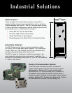
Control Board
Communication Ports
RS232/485 and TTL Ports Standard
Data Transmission Probus, DeviceNet, Modbus RTU, Modbus+, Metasys, Ethernet (Some Devices are External)
Main Protective
Functions
Current Limit, Overcurrent, Overvoltage, Undervoltage, Load-Side Short Circuit, Load-Side Ground Fault, Armature Short; Overtorque,
ASD Overload, Motor Overload, Heatsink Overheat, Open Output Phase, Loss of Feedback, CPU Error, Communications Error
Soft Stall Automatic Load Reduction Control During Overload
Retry Can Automatically Clear Fault Upon Trip; Programmable to 10 Tries with up to 10 Seconds Between Tries
Restart Restart into a Rotating Motor
Interface
LCD/EOI (Liquid Crystal
Display/Electronic
Operator Interface)
Backlit LCD Display; Ability to Display Multiple Parameters on One Screen; Keypad may be Operated from External Power Source;
Software is Flash Upgradeable; Includes Multi-Function Rotary Encoder
LED Indicators Run (Red)/Stop (Green), Remote/Local (Green), DC Bus Charge Indication (Red)
Keys Local/Remote, Monitor/Program, Run, Enter, ESC, Stop/Reset, Up, Down
Monitoring Main Display Shows Two Monitored Items Continuously, or Scrolls Up to 40 Items
Selectable Display Units
User-Selectable and Congurable along with Scaling Factor Multiplier; Voltage Display Selectable: Volts or %;
Current Display Selectable: Amps or %.
EOI Communication Ports RS232/485 and TTL Ports Standard
Remote-Mount Display Remote Mountable Up to 1000 Feet
Construction
Enclosure NEMA 1, IP20, Gasketed and Filtered
Panel Construction Free-Standing, Front-Maintenance Type, Top or Bottom Access for Motor and Power Cables
Cooling Forced-Air Cooled Top-Mounted Fans may be Removed During Shipment or Installation
Color ANSI-61 Gray
Ambient Conditions
Ambient Temperature -10 to 40°C (-14 to 104°F)
Humidity Max. 95% (Non-Condensing)
Altitude 1000 Meters (3300 Feet) Above Sea Level or Less
Installation Indoor, No Direct Sunlight, Protect from Corrosive Gases and/or Explosive Gases
Standards
Electrical Compliance NEC, ANSI