


2.4.1 Removable angles or eye bolts shall be provided at the top of the structure for lifting.
2.4.2 Optional removable sill channels shall be available.
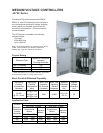
3. Power Bus
3.1 Horizontal power bus shall be located at the center rear of the cubicle, in the same location as
other JK Series controllers.
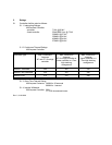
3.2 Horizontal power bus ratings of 1200 and 2000 amperes shall be available. Bus sizes shall
match those provided in other JK Series controllers.
3.3 Horizontal power bus shall be braced for 50kA RMS symmetrical.
3.4 Horizontal power bus shall be tin plated as standard with silver plating optional.
3.5 Bare copper 1/4 x 2 inch horizontal ground bus shall be available and the location shall match
other JK Series controllers.
3.6 Vertical power bus feeding 720 ampere controllers shall be 3/8 x 2 inch tin plated copper. Silver
plating shall be optional.
3.7 Horizontal power bus shall be front accessible by removing or swinging open a panel.
4. Medium Voltage Controllers - 720 Amperes
4.1 Medium Voltage Controller Compartment
4.1.1 The medium voltage controller compartment for controllers rated 720 amperes shall consist
of an isolation switch (4.2), a fixed mounted vacuum contactor (4.3), three fixed mounted power
fuses (4.4), three current transformers and a control power transformer with primary fuses.
Optionally a second control or potential transformer with primary fuses may be provided.
4.1.2 Internal power connections between power components shall be made using either high
voltage cable or bus bars.
4.1.3 Connection of customer's outgoing load cables shall be made to terminals mounted on the
left side of the medium voltage compartment. It shall be possible to terminate outgoing load
cables without the removal of major components such as the vacuum contactor and power fuses.
Sufficient wire bending space shall be provided for terminating shielded cables as large as 2-
500MCM per phase, top or bottom entry.
4.1.4 A zero sequence current transformer for ground fault sensing when required shall be
provided. It shall be located such that factory installed internal power cables from all three
phases shall pass through its window. Ground current sensors for Toshiba 2E ground fault
module and Multilin ground fault relay shall be available as a minimum.
4.1.5 Three current transformers for metering and relaying shall be provided. These shall be of
the window type with burden capacity as required for operating the various meters and relays.
4.1.6 Control power and optional potential transformers shall be of the encapsulated type with
integral primary fuses. All transformers shall be rated 60kV BIL. Primary side of transformers
shall be wired to the load side of the main controller power fuses. Transformers shall be
arranged to provide easy access for replacement of primary fuses.