User’s Manual 2-2
The Grand Tour
Left side
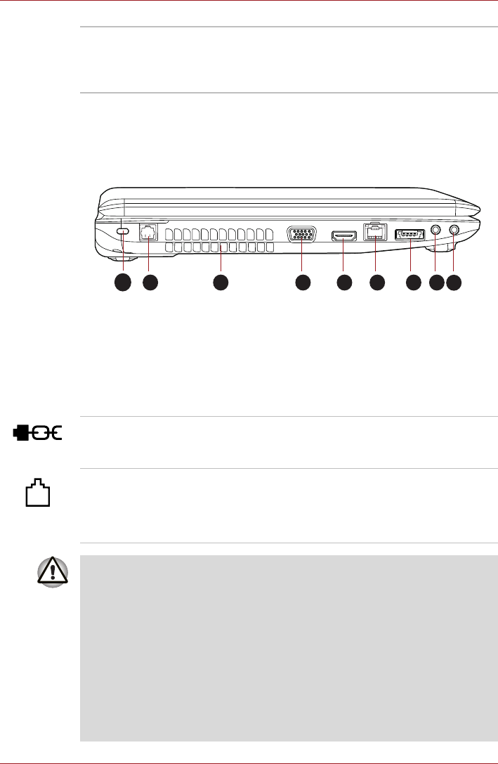
The following figure shows the computer’s left side.
* Provided with some models.
Figure 2-2 The left side of the computer
System indicators These LED indicators allow you to monitor the
status of various computer functions and are
described in more detail within the System
indicators section.
1. Security lock slot 6. LAN jack
2.Modem jack* 7.eSATA/USB combo port
3. Cooling vents 8. Microphone jack
4. External monitor port 9. Headphone jack
5. HDMI port*
1
2 3
4 5 6 7 8
9
Security lock slot A security cable can be attached to this slot and
then connected to a desk or other large object in
order to deter theft of the computer.
Modem jack The modem jack lets you use a modular cable to
connect the modem directly to a telephone line.
Some models are equipped with a modem jack.
■ Connection to any communication line other than an analog phone line
could cause a PC system failure.
■ Connect the built-in modem only to ordinary analog phone lines.
■ Never connect the built-in modem to a digital line (ISDN).
■ Never connect the built-in modem to the digital connector on a
public telephone or to a digital private branch exchange (PBX).
■ Never connect the built-in modem to a key telephone system for
residences or offices.
■ Avoid using your computer modem with the telephone cable connected
during an electrical storm. There may be a remote risk of electric shock
from lightning.


