


4 Replacement Procedures
Satellite A660/ProA660 Series Maintenance Manual 4-2
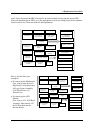
to this chart, determine the FRUs that need to be removed before removing the suspect FRU.
After you determine those FRUs, go to the appropriate sections according to the section numbers
shown in the boxes. Then start removal and replacement.
4.2 Battery 4.3 HDD 4.4 Memory
4.5 Keyboard
4.6 TV Tuner
Card and WLAN
4.7 ODD module
(Tray-load)
4.8 Logic Upper
Assembly
4.10 FeliCa Card
4.12 Touch Pad Board
4.13 Speakers and
Speaker Cushions
4.9 ODD module
(Slot-load)
4.14 Indicator
Board
4.15 USB Board
4.16 Bluetooth
4.18 TV Tuner
Antenna
4.19 Power
Membrane
4.20 Display Assembly
4.21 Motherboard
Assembly
4.22 Thermal
Module
4.24 LCD Bezel
4.25 LCD Panel
4.26 Web Camera
4.23 CPU
4.27 WLAN Antennas
4.28 LCD Panel Hinges
4.29 LVDS Cable
4.11 Fingerprint
Scanner Bracket
4.17 Thermal Fan
How to use the chart (two
examples):
• For removing the Motheroard:
First, remove parts from 4.8
Keyboard Cover & Keyboard,
4.9 Logic Upper Assembly,
4.16 WLAN card, 4.15
Thermal Fan.
• For removing the LCD
Module:
First, remove 4.21 LCD Bezel
Assembly, then remove 4.22
the LCD module and the
Inverter Board.
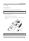
4.2 Battery 4.3 HDD 4.4 Memory
4.5 Keyboard
4.6 TV Tuner
Card and WLAN
4.7 ODD module
(Tray-load)
4.8 Logic Upper
Assembly
4.10 FeliCa Card
4.12 Touch Pad Board
4.13 Speakers and
Speaker Cushions
4.9 ODD module
(Slot-load)
4.14 Indicator
Board
4.15 USB Board
4.16 Bluetooth
4.18 TV Tuner
Antenna
4.19 Power
Membrane
4.20 Display Assembly
4.21 Motherboard
Assembly
4.22 Thermal
Module
4.24 LCD Bezel
4.25 LCD Panel
4.26 Web Camera
4.23 CPU
4.27 WLAN Antennas
4.28 LCD Panel Hinges
4.29 LVDS Cable
4.11 Fingerprint
Scanner Bracket
4.17 Thermal Fan