


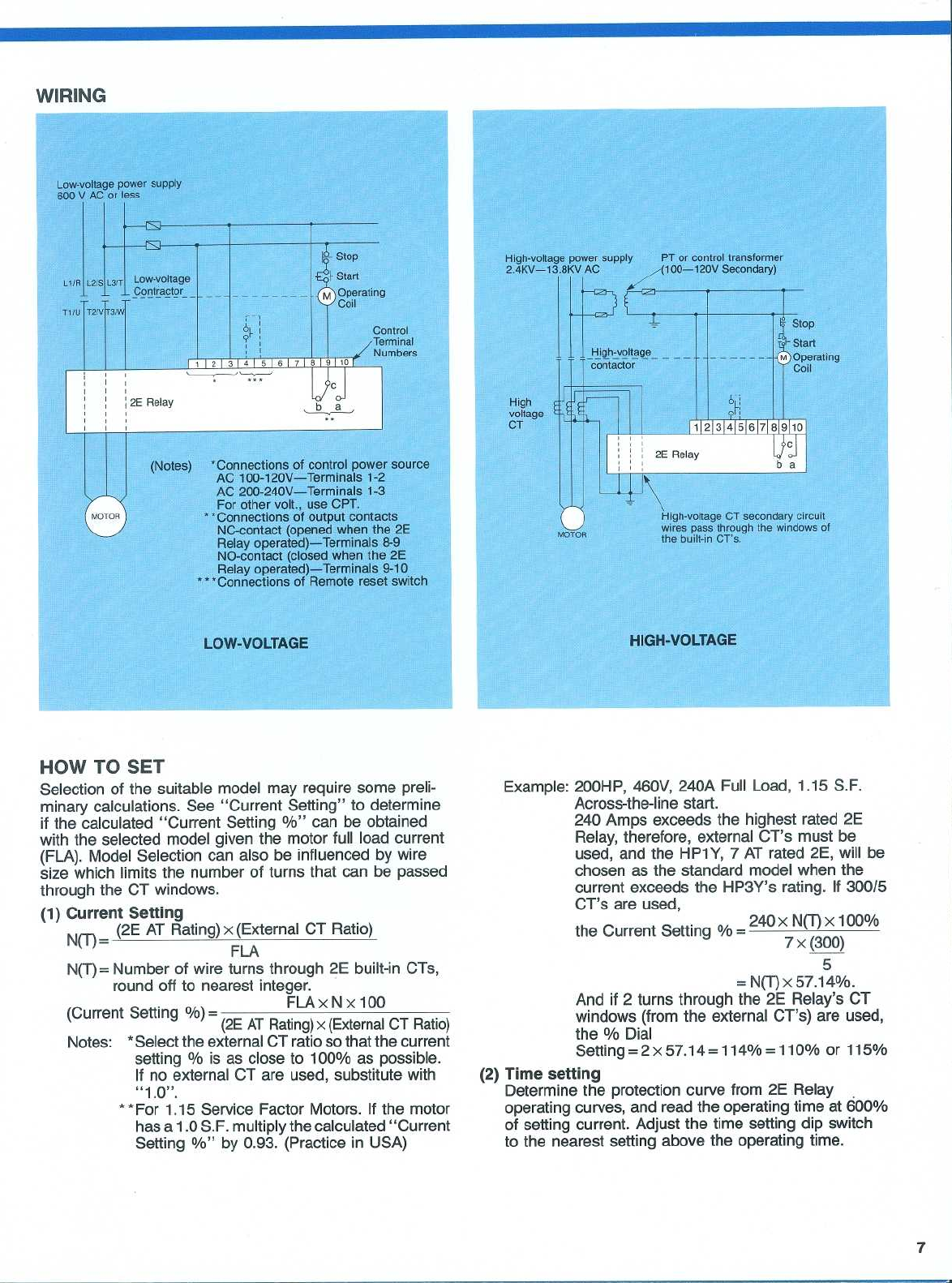
WIRING
Low-voltage
power
supply
600
V
AC
or
less
HOW
TO
SET
LOW-VOLTAGE
(Notes)
*Connections
of
control
power
source
AC
100-120V-Terminals
1-2
AC
200-24®V-Terminals
1-3
For
other
volt
.,
use
CPT
.
`"Connections
of
output
contacts
NC-contact
(opened
when
the
2E
Relay
operated)-Terminals
8-9
NO-contact
(closed
when
the
2E
Relay
operated)-Terminals
9-10
-
Connections
of
Remote
reset
switch
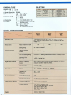
Selection
of
the
suitable
model
may
require
some
preli-
minary
calculations
.
See
"Current
Setting"
to
determine
if
the
calculated
"Current
Setting
%"
can
be
obtained
with
the
selected
model
given
the
motor
full
load
current
(FLA)
.
Model
Selection
can
also
be
influenced
by
wire
size
which
limits
the
number
of
turns
that
can be passed
through
the
CT
windows
.
(1)
Current
Setting
Nk
I
)
®
(2E
AT
Rating)
x
(External
CT
Ratio)
FLA
N(T)=Number
of
wire
turns
through
2E
built-in
CTs,
round
off
to
nearest
integer
.
(2E
AT
Rating)
x
(External
CT
Ratio)
Notes
:
"Select
the
external
CT
ratio
so
that
the
current
setting
%
is
as
close
to
100%
as
possible
.
If
no
external
CT
are
used,
substitute
with
"1 .0"
.
"For
1
.15
Service
Factor
Motors
.
If
the
motor
has
a
1
.0
S
.F
.
multiply
the
calculated
"Current
Setting
%"
by 0
.93
.
(Practice
in
USA)
High-voltage
power
supply
PT
or
control
transformer
2
.4KV-13
.8KV
AC
(100-120V
Secondary)
High-voltage
CT
secondary
circuit
wires
pass
through
the
windows
of
the
built-in
CT's
.
HIGH-VOLTAGE
Example
:
200HP,
460V,
240A
Full
Load,
1
.15
S
.F
.
Across-the-line
start
.
240
Amps
exceeds
the
highest rated
2E
Relay,
therefore, external
CT's
must
be
used,
and
the
HP1Y,
7
AT
rated
2E,
will
be
chosen as
the
standard
model
when
the
current
exceeds
the
HP3Y's
rating
.
If
300/5
CT's
are
used,
the
Current
Setting
%
=
240
x
N(T)
x
100%
7 x
(300)
5
N(T)
x
57
.14®/0
.
And
if
2
turns
through
the
2E
Relay's
CT
windows
(from
the
external
CT's)
are
used,
the
%
Dial
Setting
= 2
x
57
.14
=114%=110%
or
115%
(Current
Setting
%)=
FLAx
N
x 100
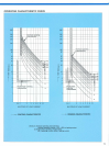
(2)
Time
setting
Determine
the
protection
curve
from
2E
Relay
operating
curves,
and
read
the
operating
time
at
600%
of setting
current
.
Adjust
the
time
setting dip
switch
to
the
nearest
setting
above
the
operating
time
.