


TOSHIBA
6F9EOO86
0
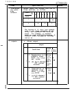
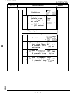
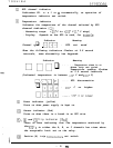
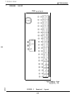
RTD channel indicator
Indicates CR. NO.’
s 1 to
8
incrementally, on operation of
temperature indicator set switch.
0
Temperature indicator
Indicates the temperature of the channel selected by RTD
channel indicator
(0)
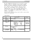
. Measuring range: -20°
C to
+200°
C
(1"
C step)
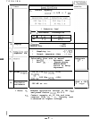
. Display: Depends on how RTD is used, for examnle:
Indicator Meaning
Channel
-f
q
r1l-l
I-1
. . . . . RTD not used
When the following indicators flashes at 0.8 second
intervals, some abnormality has happened:
Indicator
cl
no
Meaning
q
. . . . . Temperature rises to or
above trip set point.
Temperature reading flashes
at 0.8 second intervals.
(Indicated temperature is between
-20'
C and
200"
C)
,I
Fj
. . . . .
RTD disconnection
q
mmm
. . . . .
200°
C or higher
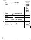
0
Power indicator (yellow)
Turns on when power supply is kept on.
@
Sensor indicator (Red)
Turns on when there is a break in an RTD wire.
0,
@
and
(3
Trip indicator
(Red)
Turns on when indicating that the temperature monitored by
the
RTD'S;
in either the A, B, or C channels has risen above
the acceptable limit set on the relay.
@
Section.(A) trip temoerature set switch
-a
-