Programmable Controllers
Rev 051115
Ethernet Setup for the S2T
Ethernet communications with the S2T CPU is done through the GEN651A Ethernet module.
Prior to using this module, it must be configured using the EtherSetup_E setup software. The
EtherSetup_E software is used to configure the network parameters (IP Address, Subnet
Mask, and Multicast Addresses) in the GEN651A Ethernet module. When all the following
setup steps described below are completed, Ethernet connection to the S2T through the
GEN651A Ethernet module will be possible. There are two methods of connection:
● T-PDS (Toshiba Program Development Software). ● UDP/IP Socket Interface.
Setup GEN651 Ethernet Module
This module must be setup 1
st
before either of the connections methods are possible.
1, Install the EtherSetup_E software on an MS Windows computer. See the installation
instructions in the User’s Guide for the Ethernet Module Parameter Setting Tool, 6F8C1103.
2
,
Set the network parameters in the GEN651A module.
2.1 Set the DIP switches on the front of the EN6651A to enable setting the network
parameters from the EtherSet_E. Set DIP Switches 7 & 8 to ON (Note: 7 & 8 are the top
two switches).
2.2 Mount the EN651A on the S2T rack, then turn on power.
2.3 Connect PC and EN6651A with the V-Tool cable (standard RS232C cross cable).
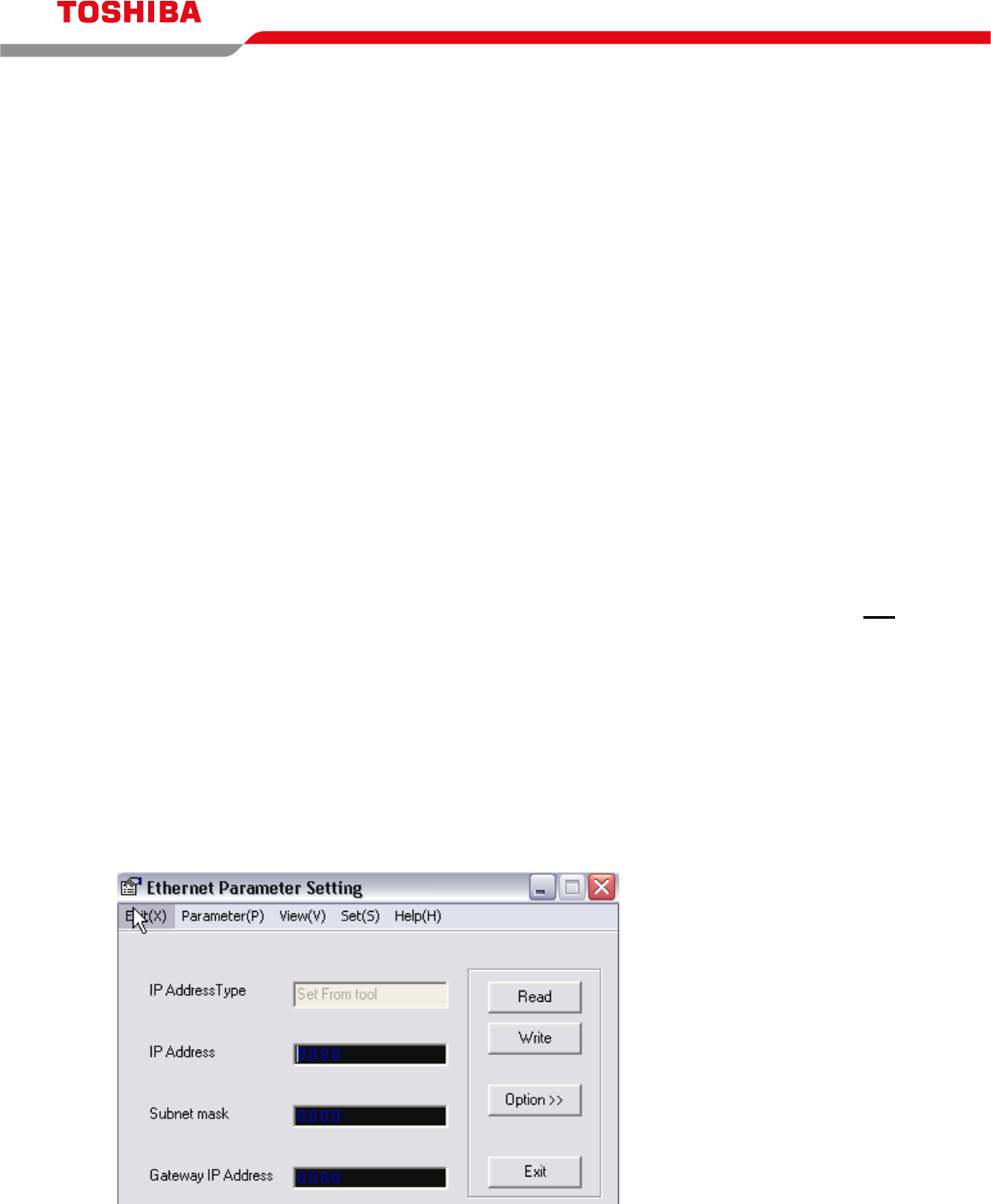
2.4 Run the EtherSet_E software on the PC.
2.5 Click the Read button on the EtherSetup_E screen. The current settings are read from
the GEN651A and are displayed on the screen.
On reading a module for the
1
st
time, settings will appear as
shown to the left.


