


Page 2
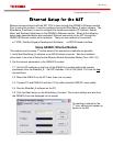
2.6 Click the Option button. Set the required parameters, then click the Write button to
write into GEN651A module.
2.7 Close the EtherSetup_E software. DIP Switches 7 and 8 must be left in the ON position
for T-PDS to work through the GEN651A module.
2.8 Cycle Power on the GEN651A module.
The new IP address will not be valid until
power is cycled on the module.
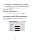
This completes setup of the GEN651A Ethernet module. If the EtherSetup_E can not establish
communications with the GEN651A, please make sure:
1. The computer is connected directly to the GEN651A using as RS232 cross cable.
2. The EtherSetup_E software is using the correct Com Port setting.
3. No other computer software is running that uses the computer’s RS232 port.
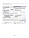
T-PDS Setup
In addition to setting up the Ethernet module, network parameters must be setup in two
additional places; the computer’s Ethernet card and the T-PDS software.
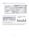
Assume the following settings were made in the EN651A Ethernet module with the
EtherSetup_E software.