


43
Others
English Français Español Deutsch Italiano
Português
Svenska
42
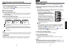
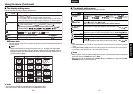
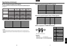
■ CONTROL terminal
● Pin assignment
7
6
8
5
4
3
2
1
Signal Name
RXD
CTS
DSR
GND
RTS
N.C
TXD
GND
Pin No.
1
2
3
4
5
6
7
8
Description
Receiving data
Consent to send
Data set ready
Signal ground
Request to send
No connection
Sending data
Signal ground
Mini DIN 8 pin connector
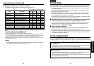
● Interface format
1 Communication method RS-232C, 9600bps, No Parity, Data Length: 8 bits;
Stop Bit Length: 1 bit
2 Communication format STX (02h) Command (3Byte) ETX (03h)
Only 1 command valid per communication.
3 Data format For input commands, only ASCII-compliant all-uppercase
alphanumeric characters supported.
4 Replies Acknowledge ACK (06h) CR (0Dh) Data ... Normally ended
ACK (06h) ESC (1Bh) ... Aborted
No acknowledge NAK (15h)
If commands are to be sent consecutively, wait for the response from the projector
before sending the next command.
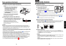
● Main Commands
Item Command
Computer input select IN1
DVI input select IN2
Video input select IN3
S-video input select IN4
YP
B/CBPR/CR input select IN5
Item Command
Power on PON
Power off PSD
Icon display on MO0
Icon display off MO1
Auto setting (RGB input) PAT
Status display on DON
Status display off DOF
Note
• Contact your dealer for control cable and other commands.
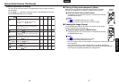
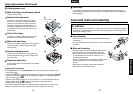
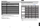
Specifications (Continued)
■ Pin arrangement for the DVI-D terminal
Pin No.
1
2
3
4
5
6
7
8
9
10
11
12
13
14
15
Pin description
T.M.D.S. data 2–
T.M.D.S. data 2+
T.M.D.S. data 2/4 shield
T.M.D.S. data 4–
T.M.D.S. data 4+
DDC clock
DDC data
Analog vertical sync signal
T.M.D.S. data 1–
T.M.D.S. data 1+
T.M.D.S. data 1/3 shield
T.M.D.S. data 3–
T.M.D.S. data 3+
+5V power supply
GND(+5V, H Sync & V Sync)
Pin description
Hot plug detection
T.M.D.S. data 0–
T.M.D.S. data 0+
T.M.D.S. data 0/5 shield
T.M.D.S. data 5–
T.M.D.S. data 5+
T.M.D.S. clock shield
T.M.D.S. clock+
T.M.D.S. clock–
Pin No.
16
17
18
19
20
21
22
23
24
D V I - D
24
8
1
16
17
9
DVI DIGITAL connector