


2322
Preparations
p.52
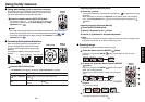
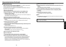
Audio amplifier, etc. DVD video recorder, etc.
Video recorder,
DVD player, etc.
Video recorder, etc.
Conversion
adapter BNC-pin
(not supplied)
Monitor cable Mini
D-sub 15P-BNC
(not supplied)
To audio input
White (L)/Red (R)
To audio
output
White (L)/
Red (R)
AV cable
(not supplied)
S-video cable
(not supplied)
To S-video
output
To video
output
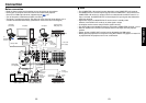
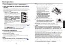
Before connection
• Read the owner’s manual of the device you are connecting to the projector.
• Some types of computer cannot be used or connected to this projector.
Check for an RGB output terminal, supported signal
p.50
, etc.
•Turn off the power of both devices before connecting.
• The figure is a sample connection. This does not mean that all of these devices can or
must be connected simultaneously. (Dotted lines mean items can be exchanged.)
Notes
• The COMPUTER 1 IN terminal functions identically to the COMPUTER 2 IN terminal.
• The MONITOR OUT terminal outputs signals from the COMPUTER 1 IN terminal or the
COMPUTER 2 IN terminal, or outputs Y/P
B/PR as selected with the INPUT button. If no
input is selected, the MONITOR OUT terminal outputs the input signals last selected for
each input terminal
• Signals are output from MONITOR OUT terminal even in standby mode.
However, from AUDIO OUT terminal, no audio signal is output.
•A computer monitor cannot accept Y/P
B/PR signals correctly.
• The AUDIO IN terminal doubles for devices connected to COMPUTER terminals 1 and 2.
• When an AUDIO OUT terminal is connected, sound is not output from the projector
speaker.
• Output volume of AUDIO OUT terminal can be adjusted by the VOL button.
•Moving pictures played back on computers using DVD software may appear unnatural if it
is projected with this projector, but it is not a malfunction.
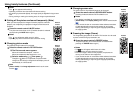
Connection
Computer
(for control)
Computer
To
RS-232C
terminal
Audio cable
(not supplied)
To audio
output
Control cable
RGB cable
(supplied)
To RGB
output
Computer
Audio cable
(not supplied)
Audio cable
(not supplied)
To audio
output
To Y/CB/CR
output
Green (Y)/Blue
(C
B)/Red (CR)
To audio output
White (L)/Red (R)
Audio cable
(not supplied)
To audio
output
Audio cable
(not supplied)
RGB cable
(not supplied)
To RGB
output