


Chapter 3. Identifying External Components
This Chapter describes the front panel, rear panel and LED indicators of the Switch.
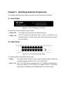
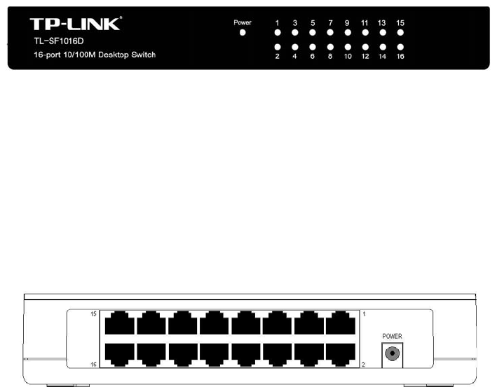
3.1 Front Panel
Figure 3-1 TL-SF1016D Switch Front Panel
The Switch’s LEDs are located on the front panel.
¾ Power LED:
This indicator will light up when the Switch powers on.
¾ LEDs (1-16):
One LED indicator will light green when a device is connected to the
corresponding port. It flashes when data is being transmitted or received
on the connection.
3.2 Rear Panel
Figure 3-2 TL-SF1016D Switch Rear Panel
The following parts are located on the rear panel:
¾ Power:
The Power socket is where you will connect the power adapter. Please use
the power adapter provided with this TL-SF1016D Switch.
¾ Port (1-16):
The TL-SF1016D Switch is equipped with 16 10/100Mbps Auto-Negociation
RJ45 ports where you will connect your network devices. The working
status can be indicated by the corresponding LEDs on the front panel.