


T
L
-
S
G
1
0
2
4
1
0
00
M
bp
s
1
0
0M
b
p
s
P
ow
e
r
F
A
N
1
F
A
N
2
2
4
-P
o
r
t
G
i
g
a
b
i
t
S
w
i
t
c
h
3
5
7
2
4
6
8
1
1
1
3
1
5
1
0
1
2
1
4
1
6
1
9
2
1
2
3
1
8
2
0
2
2
24
9
1
7
L
i
n
k
A
c
t
3
4
TL-SG1008/TL-SG1016/TL-SG1024
Gigabit Ethernet Switch User's Guide
TL-SG1008/TL-SG1016/TL-SG1024
Gigabit Ethernet Switch User's Guide
× LED indicators for monitoring power, link, activity, speed, fan (only for
TL-SG1024)
× Rack-mountable steel case
× Internal power supply
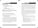
Chapter 2: Installation
2.1 Mounting the Switch on a Desk
Before place the Switch on a desk, attach four rubber footpads to the flutes on
the Switch bottom, then lay the Switch on the desktop, where can be have as
much as 5kg placed on top.
Note: Make sure there is a grounded AC outlet within 1.5 meters, and
working well.
Make sure there is free space for radiating heat and air.
Make sure not to place anything to heavy on top of the switch.
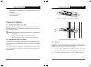
2.2 Mounting the Switch in a Rack
The dimension of TL-SG1008/TL-SG1016/TL-SG1024 is designed according
to the standard 19” rack-mountable steel case of Electronic Industries
Association.
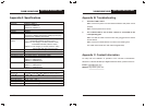
Turn off all the equipment connected to the Switch before mounting it in the
rack, then rivet the two “L” brackets onto each side of the Switch, fasten it with
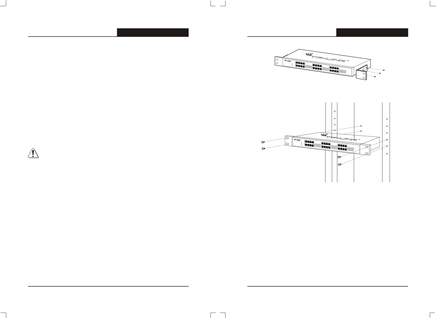
screws in the rack.
Figure 2-1 Rivet the “L” brackets onto the Switch
Figure 2-2 Fasten the Switch in the rack
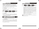
2.3 Power on
TL-SG1008/TL-SG1016/TL-SG1024 8/16/24-port Gigabit Ethernet Switch is
powered by AC power supply. Powering on the Switch, it will automatically
initialize and its LED indicators should respond as follows:
1) All of the Link/Act, 100Mbps and 1000Mbps LED indicators will flash
momentarily for one second, which represent a resetting of the system.
2) The Power and FAN LED indicator (only for TL-SG1024) will light up.
TL
-
S
G
1
0
2
4
1
0
0
0
M
b
p
s
1
0
0
M
b
p
s
P
o
w
e
r
F
AN
1
F
A
N
2
2
4
-
P
o
rt
G
i
g
a
bi
t
S
w
i
t
c
h
3
5
7
2
4
6
8
1
1
1
3
1
5
1
0
1
2
1
4
1
6
1
9
2
1
2
3
1
8
2
0
2
2
2
4
9
1
7
L
i
n
k
A
c
t