


T
T
T
r
r
r
a
a
a
n
n
n
s
s
s
c
c
c
e
e
e
n
n
n
d
d
d
I
I
I
n
n
n
d
d
d
u
u
u
s
s
s
t
t
t
r
r
r
i
i
i
a
a
a
l
l
l
C
C
C
F
F
F
C
C
C
a
a
a
r
r
r
d
d
d
(
(
(
T
T
T
S
S
S
1
1
1
2
2
2
8
8
8
M
M
M
~
~
~
1
1
1
6
6
6
G
G
G
C
C
C
F
F
F
1
1
1
0
0
0
0
0
0
I
I
I
)
)
)
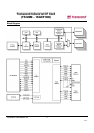
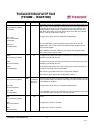
Transcend Information Inc.
V1.1
12
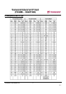
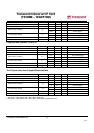
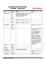
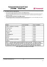
Signal Name
Dir.
Pin
Description
-VS1
-VS2
(PC Card Memory Mode)
-VS1
-VS2
(PC Card I/O Mode)
-VS1
-VS2
(True IDE Mode)
O
33
40
Voltage Sense Signals. -VS1 is grounded on the Card and sensed by the Host
so that the CompactFlash Storage Card CIS can be read at 3.3 volts and -
VS2 is
reserved by PCMCIA for a secondary voltage and is not connected on the Card.
This signal is the same for all modes.
This signal is the same for all modes.
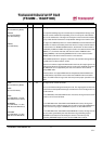
-WAIT
(PC Card Memory Mode)
-WAIT
(PC Card I/O Mode)
IORDY
(True IDE Mode – Except
Ultra DMA Mode)
-DDMARDY
(True IDE Mode – Ultra DMA
Write Mode)
DSTROBE
(True IDE Mode – Ultra
DMA Read Mode)
O
42 The -WAIT signal is driven low by the CompactFlash Storage Card to
signal the
host to delay completion of a memory or I/O cycle that is in progress.
This signal is the same as the PC Card Memory Mode signal.
In True IDE Mode, except in Ultra DMA modes, this output signal may be used
as IORDY.
In True IDE Mode, when Ultra DMA mode DMA Write is active, this signal is
asserted by the host to indicate that the device is read to receive Ultra DMA
data-in bursts. The device may negate -DDMARDY to pause an Ultra DMA
transfer.
In True IDE Mode, when Ultra DMA mode DMA Write is active,
this signal is the
data out strobe generated by the device. Both the rising and falling edge of
DSTROBE cause data to be latched by the host. The device may stop
generating DSTROBE edges to pause an Ultra DMA data-out burst.
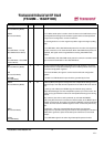
-WE
(PC Card Memory Mode)
-WE
(PC Card I/O Mode)
-WE
(True IDE Mode)
I
36 This is a signal driven by the host and used for strobing memory
write data to the
registers of the CompactFlash Storage Card when the card is configured in the
memory interface mode. It is also used for writing the configuration registers.
In PC Card I/O Mode, this signal is used for writing the configuration registers.
In True IDE Mode, this input signal is not used and should be
connected to VCC
by the host.