


2
CSEFE10xx-10x
24-Hour Technical Support: 1-800-260-1312 -- International: 00-1-952-941-7600
Installation
CAUTION: Wear a grounding device and observe electrostatic discharge
precautions when setting the jumper or when installing the media converter.
Failure to observe this caution could result in damage to, and subsequent
failure of, the media converter.
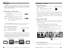
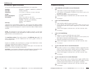
Set the Hardware / Software Jumper
• The hardware/software jumper (J2) is located on
the circuit board.
• Use small needle-nose pliers to move the jumper
to the desired position.
Hardware The media converter mode is determined by
the switch settings (see below).
Software The media converter mode is determined by
the most-recently saved, on-board
microprocessor settings.
software mode
hardware mode
H
S
H
S
J2
J2
The Link Pass-Through and speed switches are located on the side of the
media converter. Use a small screwdriver to set the recessed switches.
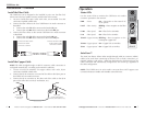
Set Link Pass-Through (switch 1)
Switch 1 sets the Link Pass-Through feature:
up = Enable Link Pass-Through.
down = Disable Link Pass-Through.
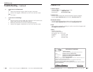
Link Pass-Through is a troubleshooting feature that allows the media converter
to monitor both the fiber and copper RX (receive) ports for loss of signal. In
the event of a loss of an RX signal on one media port, the media converter will
automatically disable the TX (transmit) signal of the other media port, thus,
“passing through” the link loss. This feature prevents the loss of valuable data
unknowingly transmitted over an invalid link.
Speed: up = 100 Mb/s
Link Pass-Through: up = Enable
1 2
4
1
Media
Converter A
Media
Converter B
Near-End
Device
Far-End
Device
original fault
on the copper link
media converter B
disables the copper lin
k
media converter A
disables the fiber TX link
3
2
media converter B
loses the fiber RX link
techsupport@transition.com -- Click the “Transition Now” link for a live Web chat
3
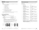
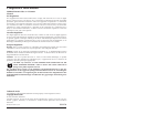
Install the Slide-In-Module
CAUTION: Slots in the PointSystem™ chassis without a slide-in-module
installed MUST have a protective plate covering the empty slot for Class A
and/or Class B compliance.
To install the CSEFE10xx-10x media converter slide-in-module:
1. Locate an empty installation slot on the PointSystem™ chassis.
2. Carefully slide the slide-in-module into the installation slot, aligning the
module with the installation guides.
3. Ensure that the module is firmly seated against the back of the chassis.
4. Push in and rotate the panel fastener screw (attached to the slide-in-
module) to secure the module to the chassis front.
CFMFF100
CFMFF100
CETCF100
CFETF100
CFMFF100
SPD
PWR
FRX
CRX
FLNK
CLNK
100BASE-TX
RX
TX
100BASE-FX
Link Alert
E
D
0
50½
LA
PWR
RXF
RXC
LNK
COL
LKS
PWR
LKM
10BASE-2
10BASE-FL
LKS
PWR
LKM
LKS
PWR
LKM
Multimode
Singlemode
TX
RX
TX
RX
Multimode
Singlemode
TX
RX
TX
RX
Multimode
Singlemode
TX
RX
TX
RX
I
0
TERM
INIT
RX
TX
LNK
PWR
CPSMM120
SERIAL
10BASE-T
R
E
S
E
T
I
0
PWR
SX
10
TX
100ACT
panel fastener screw
Power the Media Converter
The CSEFE10xx-10x slide-in-module is powered through the Transition
Networks PointSystem™ chassis.
Installation -- Continued
Set the Speed (switch 2)
Switch 2 sets the speed for both the twisted-pair
copper and fiber links:
up = copper and fiber links are at 100Mb/s.
down = copper and fiber links are at 10 Mb/s.
NOTE: The CSEFE10xx-10x media converters are fully compliant with
10Base-T, 100Base-TX, and 100Base-FX standards and, therefore, can be
connected to any compliant 10Base-T, 100Base-TX, and 100Base-FX devices.
The CSEFE10xx-10x media converters are NOT 10Base-FL compliant and,
therefore, must be connected to another CSEFE10xx-10x media converter in a
10Mb/s network.
Speed: up = 100 Mb/s
Link Pass-Through: up = Enable
1 2