


6
SBFTF1010-130
Tech Support: 1-800-260-1312 International: 00-1-952-941-7600, 24 hours
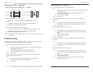
Connecting power to the bridging media converter
AC/DC:
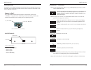
1. Connect the barrel connector of the adapter to the power port of the bridging
media converter (located on the back of the converter shown below).
2. Connect the power adapter plug into AC power: if all the configuration switches
are in the UP position, the port LEDs will flicker during the initialization
process and then go OFF.
Note: The power-on LED will be lit (ON).
Chassis Rear
Barrel-Connector
Power Receptacle
Installation --continued
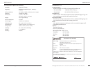
Installing the twisted-pair copper cable
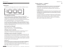
1. Locate or build an IEEE 802.3 compliant 10Base-T or 100Base-TX cables, with
male RJ-45 connectors installed onto both ends.
2. Connect the RJ-45 connector at one end of the cable to the RJ-45 port on the
bridging media converter as shown below.
3. Connect the RJ-45 connector at the other end of the cable to the RJ-45 port on the
other device (switch, workstation, etc.) as shown below.
Note: The MDI (straight-through) cable or the MDI-X (crossover) cable connection is
configured automatically, according to network conditions.
RJ-45 Port
Transceiver
RJ-45 Port
Switch,Workstation, etc.
Cable Specifications
Copper cable (10Base-T/100Base-TX)
Ensure that the correct cable type is installed to support the highest speed and mode of
operation. Though category 3 cable is adequate for a 10Base-T installation, category 5
cable is recommended, since category 3 cable DOES NOT support 100Base-TX.
Category 3: (minimum requirement for 10 Mbps operation)
Gauge: 24 to 22 AWG
Attenuation: 11.5 dB/100m @ 5-10 MHz
Maximum cable distance: 100 meters
Category 5: (minimum requirement for 100 Mbps operation)
Gauge: 24 to 22 AWG
Attenuation: 22.0 dB/100m @ 100 MHz
Maximum cable distance: 100 meters
• Straight-through (MDI) or crossover (MDI-X) cable may be used.
• Shielded (STP) or unshielded (UTP) twisted-pair cable may be used.
• Pins 1/2 and 3/6 are the two active pairs in an Ethernet network.
• Use only dedicated wire pairs for the active pins:
(e.g., blue/white & white/blue, orange/white & white/orange, etc.)
• Do not use flat or silver satin wire.
7
SBFTF1010-130
techsupport@transition.com -- Click the “Transition Now” link for live Web chat.
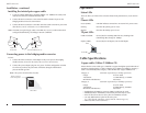
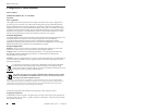
Operation
Status LEDs
There are three (3) LEDs on the converter chassis front panel and two (2) on each TP
port.
Chassis LEDs
Power (PWR): LED ON indicates connection to an external AC power source
Primary: ON when the primary port is in use
Backup: ON when the backup port is in use
TP port LEDs
LINK/ACT/SPD: Green (ON) for 100 Mbps and Link/Act; Flashing when
transmitting data; Orange for 10Mbps
Duplex (DPX): Green (ON) for full duplex; OFF for half duplex
TP Port
Du
p
Li nx/Act/SPD