


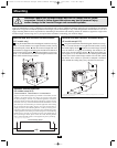
To avoid overloading your Inverter/Charger, match the power requirements of the equipment you plan to run at any one time (add their total
watts) with the output wattage capacity of your Inverter/Charger model (see Specifications). Do not confuse “continuous” wattage with
“peak” wattage ratings. Most electric motors require extra power at start-up (“peak wattage”) than required to run continuously after start-
up, sometimes over 100% more. Some motors, such as in refrigerators and pumps, start and stop intermittently according to demand, requir-
ing “peak wattage” at multiple, unpredictable times during operation. DoubleBoost
™
Feature: Tripp Lite Inverter/Chargers deliver up to twice
their nameplate rated wattage for up to 10 seconds,* providing the extra power needed to cold start heavy-duty tools and equipment.
OverPower
™
Feature: Tripp Lite Inverter/Chargers deliver up to 150% of their name-plate rated wattage for up to 1 hour,* providing plenty
of reserve power to reliably support tools and equipment longer.
* Actual duration depends on model, battery age, battery charge level and ambient temperature.
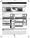
Connection for Models with Cords and Receptacles
Plug the Inverter/Charger’s AC input cord into an outlet providing 120V AC, 60Hz. power. Make sure that the circuit you connect your
Inverter/Charger to has adequate overload protection, such as a circuit breaker or a fuse. Plug your equipment into the Inverter/Charger’s AC
receptacles. Any equipment you connect to it will benefit from your Inverter/Charger’s built-in ISOBAR
®
surge protection!
Warning! Consult a qualified electrician and follow all applicable electrical codes and requirements
for hardwire connection. Disconnect both DC input and AC utility supply before attempting hardwiring.
Use wire type THHN or equivalent with minimum temperature rating of 90°C.
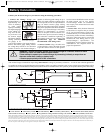
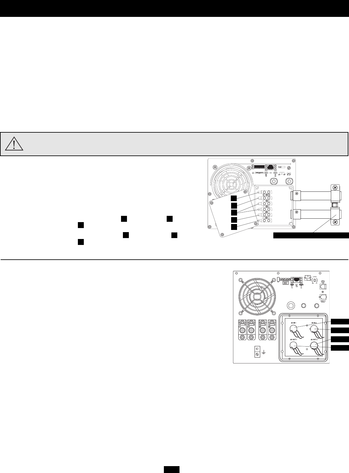
Connection for Models with Hardwire Terminals
Output Connection Requirement: UL requires that the output terminals of all hard-
wire Inverter/Charger models must be connected to UL-listed GFCI receptacles
(required receptacle manufacturer/model series: Hubbell GF8300HGW or
Leviton 6598).
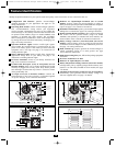
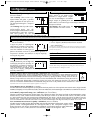
Single Input/Output Models
Input: Connect incoming wires to the hot (brown) , neutral (blue)
and ground* (green) terminals .
Output: Connect outgoing wires to the hot (black) , neutral (white)
and ground* (green) terminals .
Replace cover plate and tighten screws.* If the incoming conduit only contains two wires (hot and neutral), the incoming conduit must be bonded to the main ground lug on the unit. In any case,
the incoming conduit must be bonded to earth or vehicle ground, and the incoming conduit must be bonded to the outgoing conduit.
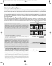
Dual Input/Output Models
Select models provide higher bypass power capacity by enabling connection of two separate
AC input sources. These two sources can be either two 120V legs split from a single 240V
service (with opposite phase on each 120V leg) or two different 120V sources. The
Inverter/Charger will only supply 120V output power and WILL NOT provide 240V output
even if it is connected to inputs from a split 240V service when in inverter mode. When the
Inverter/Charger is receiving AC power, it can supply connected loads with up to 20 amps
of power on each circuit**. When the Inverter/Charger is not receiving AC power, and has
switched to inverting DC battery power, it can supply connected loads with various amper-
age levels (see “Maximum Output AC Current” in Specifications section) on BOTH circuits.
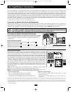
Dual input/output models provide for either: a) dual-source inputs and outputs; b) single-
source input and output; or c) single-source input and dual-source outputs (with AC OUT
2 power only available in invert mode). Connect user-supplied wire and conduit to the con-
nections as follows:
Input: Connect incoming wires to hot (black for AC IN 1, black for AC IN 2), neutral
(white for AC IN 1, white for AC IN 2) and ground (green/yellow) wires.
Output: Connect outgoing wires to hot (black for AC OUT 1, black for AC OUT 2), neutral
(white for AC OUT 1, white for AC OUT 2) and ground (green/yellow) wires.
* Single-Source or Dual-Source Input/Output Connection: As well as supplying power to connected loads, AC IN 1 also provides power to the battery charger. If you connect a large load to AC OUT 1,
you should select a more limiting battery charger setting (see “Select Battery Charger-Limiting Points”) or you may experience continual nuisance tripping of the electrical service (source) circuit
breaker which supplies AC IN 1. The Inverter/Charger will only measure the current at AC OUT 1 to automatically limit the charger rate. AC IN 2 input current is passed through to AC OUT 2 with-
out measurement. Single-Source Input/Dual-Source Output Connection: You may connect AC IN 1 and AC IN 2 to a single source to provide power to AC OUT 1 and AC OUT 2. However, the loads connected to
AC OUT 2 will not be measured for the purpose of automatic charger limitation. This could result in occasional tripping of the electrical service (source) circuit breaker. If this occurs, reduce the load on AC OUT
2 until nuisance tripping stops.
** Load circuit breaker limited
11R
1
2
3
4
5
AC Input/Output Connection
HOT IN
NEUTRAL IN
GROUND IN
GROUND OUT
HOT OUT
“FOR USE WITH COPPER WIRE ONLY”
NEUTRAL OUT
2
3
1
4
5
Note: Ground Bond Connection, Supplied
AC IN 1
AC IN 2
AC OUT 2
AC OUT 1
1
Dual-Source Input/Output*
• AC IN 1 will only provide line power to AC OUT 1.
• AC IN 2 will only provide line power to AC OUT 2.
• Inverted battery power is supplied to both AC OUT 1 and AC OUT 2.
Single-Source Input/Output*
• If you only have a single 120V AC input source, you must
connect it to AC IN 1.
• If you only have a single output circuit, you must connect it to
AC OUT 1
200310080 93-2182 RV Inverter-Charger Owner’s Manual Revision.qxd 10/17/2003 11:43 AM Page 11