11
Communications
(continued)
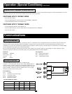
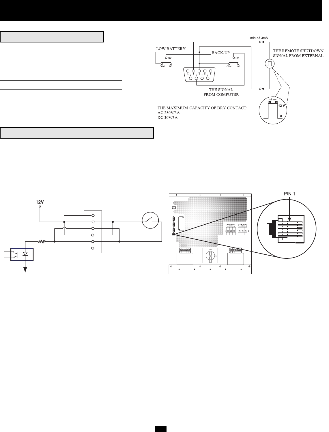
REMOTE EMERGENCY POWER OFF (EPO)
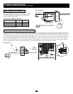
This optional feature is only for those applications which require connection to a facility's Emergency Power Off (EPO) circuit. When the UPS System
is connected to this circuit, it enables emergency shutdown of the output. Using a user-supplied cable, connect the UPS System's EPO port to a user-
supplied remote switch. The EPO port is not a phone line surge suppressor; do not connect a phone line to this port. The pin assignments for the EPO
port are shown in the following diagram. Note: if there is a short between pins 2 and 3, 2 and 5, 4 and 5, or 3 and 4, the UPS system will power off. To
reset from a Remote Emergency Power Off Shutdown, make sure there is AC line input power present, the Input Breakers are ON, and the shutdown-
signal has been removed from the EPO circuit. Press the front panel “OFF” Button for 2 to 3 seconds (until a beep is heard); this will place the UPS
System in “Bypass Mode.” Then, press the “ON” Button for one second. The UPS will re-start if AC line power is present.
Pin assignment:
X
1
2
3
4
5
6
X
DRY CONTACT INTERFACE
This female DB9 contact-closure port allows your UPS to send
contact-closure signals to indicate that it is on battery back-up
mode and if its batteries are running low. The port can also
receive a remote shutdown signal.
DRY CONTACT INTERFACE TABLE
UPS Operating Mode Pin 8,3 Pin 1,3
Normal OPEN OPEN
Back Up CLOSE *
Low Battery CLOSE CLOSE
* Inactive: may be in either state.
3 V
+
-
Pin assignment:


