


SMART 216 / 232
1
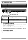
3.1 LED and button table
LED Function
Power
Power Indicator
Link
Unit is connected to the network
Remote 1 and 2
Illuminates when the respective user connects to a server
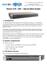
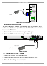
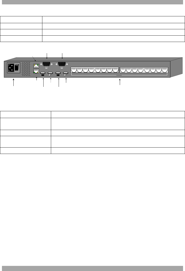
Figure 2 Smart 216 ports – side 2
3.2 Connector table
Connector Function
User 1 and User 2
KVM consoles
Connect 2 KVM consoles for two users to operate the Smart 216
RPS
Connect Minicom’s Serial Remote Power Switch
LAN
To configure and update the unit, connect to 10/100 Mbit
Ethernet.
Server ports
Connect to servers via ROCs
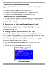
4. Pre-installation guidelines
Place cables away from fluorescent lights, air conditioners, and machines that
are likely to generate electrical noise
Place the Smart 216 on a flat, clean and dry surface or install in a rack
Ensure that the maximum distance between each computer and the Smart 216,
does not exceed 30m/100ft.
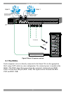
5. Connecting the system
Figure 3 illustrates the Smart 216 system overview.
Power
POWER
100-240 VAC 50/60 Hz
Server ports
I
0
1 2 3 4 5 6 7 8
Keyboard
Mouse
Monitor
USER 1
LAN (Ethernet)
port
LAN
RPS
Remote Power
Switch (RPS)
port
10 11 12 13 14 15 169
SERVER
Keyboard
Mouse
Monitor
USER 2