


4
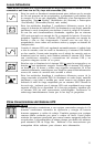
On/Standby Switch
This momentary switch controls power to the UPS receptacles.
Engage it momentarily and release it to toggle between the “ON” mode
(power ON at the UPS receptacles) and “Standby” mode (power OFF at
the UPS receptacles).
Mute/Test Switch
Use this momentary switch to do two things:
Silence the blackout alarm
Engage this switch and release it. Note: when the battery is nearly
depleted, the alarm resumes (and cannot be silenced) to alert you to
immediately shut down connected equipment.
Test your UPS’s battery charge
Leave your connected equipment ON. With your UPS plugged in and
completely turned ON, engage this switch; hold it there for 5 seconds
and release it. The UPS will momentarily switch to battery to test its
charge. The alarm will sound and the “XXX” light may turn ON if your
UPS fails a self-test and/or the UPS battery is less than fully charged.
Let the UPS charge for 12 hours and perform a second self-test. If the
light continues to stay on, contact Tripp Lite for service. CAUTION:
Do not unplug your UPS to test its batteries. This will remove safe
electrical grounding and may introduce a damaging surge into your
network connections.
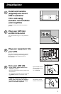
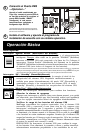
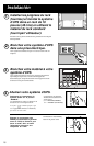
Load software and run the installation
program appropriate for your operating system.
6
* Serial port connections are optional. Your UPS will function
properly without these connections.
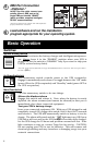
Switches
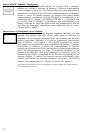
System Enable Switch
This switch activates the battery charger and intelligent microproces-
sor.
Always leave it in the “ENABLE” position when your UPS is
plugged in. Set the switch to “DISABLE” only if you store or ship your
UPS (to reduce battery drain).
*Note: The “XXX” light will flash until you engage the ON/Standby Switch to activate the “ON” mode (power ON at
the UPS receptacles).
Basic Operation
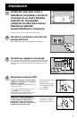
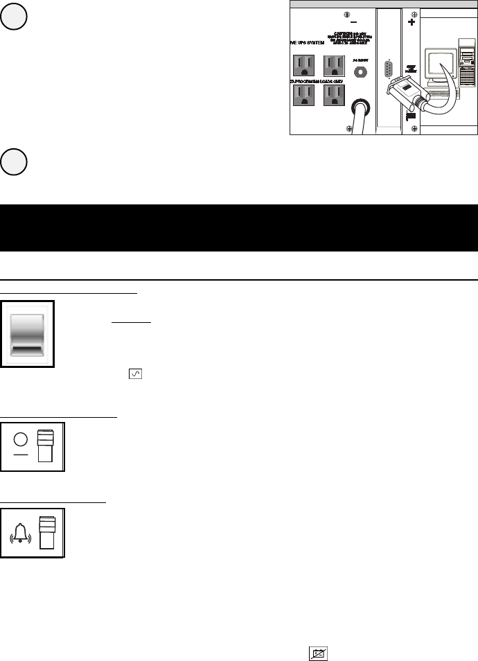
DB9 Port Connection
–Optional–*
Using Tripp Lite cable, connect your
primary server’s DB9 port to the
single DB9 port labeled “SMART”
(which provides complete intelligent
RS-232 communications).
5