


3R
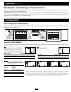
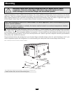
Feature Identification
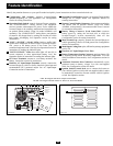
Identify the premium features on your specific model and quickly locate instructions on how to maximize their use.
Configuration DIP Switches: optimize Inverter/Charger
operation depending on your application. See Configuration
section for setting instructions.
Operating Mode Switch: controls Inverter/Charger operation.
The “AUTO/REMOTE” setting ensures your equipment
receives constant, uninterrupted AC power. It also enables the
Inverter/Charger to be remotely monitored and controlled with
an optional remote module (Tripp Lite model APSRM4, sold
separately). The “CHARGE ONLY” setting allows your batteries
to return to full charge faster by turning the inverter off which
halts battery discharging. See Operation section for setting
instructions.*
“LINE”, “INVERT”, “LOAD” LEDs: intuitive “traffic light”
signals show whether the Inverter/Charger is operating from AC
line power or DC battery power. It also warns you if the
connected equipment load is too high. See Operation section for
instructions on reading the indicator lights.
"BATT VOLTAGE" LEDs: these three lights will turn ON in
several sequences to show approximate battery level. See
Operation section for instructions on reading the indicator lights.
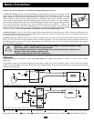
DC Power Terminals: connect to your battery terminals. See
Battery Connection section for instructions.
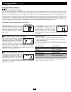
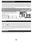
Hardwire AC Input/Output Terminals: securely connect the
Inverter/Charger to vehicle or facility electrical system input and
recommended GFCI protected output. See AC Input/Output
Connection section for instructions.
Resettable Circuit Breaker: protect your Inverter/Charger against
damage due to charger failure. See Operation section for
resetting instructions.
Remote Control Module Connector: allows remote monitoring
and control with an optional module (Tripp Lite model
APSRM4, sold separately). See remote module owner’s manual
for connection instructions.
Battery Charge Conserver (Load Sense) Dial: conserves
battery power by setting the low-load level at which the
Inverter/Charger’s inverter automatically shuts off. See
Configuration section for setting instructions.
Main Ground Lug: properly grounds the Inverter/Charger to
vehicle grounding system or to earth ground. See Configuration
section for instructions.
Multi-Speed Cooling Fan: quiet, efficient fan prolongs equipment
service life.
Hardwire AC Input/Output Cover Plate
Battery Temperature Sensing Connector: prolongs battery life
by adjusting charge based on battery temperature. Use with
cable (included on select models). See Configuration section for
details.
Automatic Generator Start Connector: automatically cycles
generator based on battery voltage. Use with user-supplied
cable. See Configuration section for details.
Ignition Switch Control Jack: use to connect the Inverter to
your vehicle's ignition switch (with user supplied cable) in order
to automatically control the Inverter with the vehicle's ignition
switch. See Operation section.
1
2
3
4
5
6
7
8
9
HOT IN
NEUTRAL IN
GROUND IN
GROUND OUT
HOT OUT
“FOR USE WITH COPPER WIRE ONLY”
NEUTRAL OUT
1
24 3
5
7
6
Front View
10
Rear View
Side Mounted,
Not Shown
Side Mounted,
Not Shown
10
11
12
13
11
8
9
13
14
12
14
* OFF - De-energizes unit and AC output on most models.
DC OFF - De-energizes unit and connects AC OUT to AC IN on select models.
15
Side Mounted,
Not Shown
15