


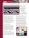

Feature Focus
200812152 95-3056
Specifications
1111 W. 35th Street • Chicago, IL 60609 USA
(773) 869-1234 • www.tripplite.com
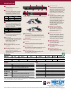
B064-032-02-IP (B064-032-04-IP is similar. B064-016-04-IP has 16 ports and LEDs.)
B054-001-USB Server Interface Module (SIM)
B054-001-PS2 Server Interface Module (SIM)
Distributed By:
Copyright © 2009 Tripp Lite. All trademarks are the sole property of their respective owners. Photos may differ slightly from final products. Tripp Lite follows a policy of continuous improvement. Specifications are subject to change without notice.
Model
Server
Ports
Maximum
Servers
(A)
Simultaneous
Users
Keyboard/Mouse
Interface
(B)
IP Access
On-Screen
Display Form Factor
NetDirector Cat5 IP KVM Switches
B064-016-04-IP
16 128 5 (4 remote) USB & PS/2 Built-In Yes 1U Rackmount
B064-032-02-IP
32 256 3 (2 remote) USB & PS/2 Built-In Yes 1U Rackmount
B064-032-04-IP
32 256 5 (4 remote) USB & PS/2 Built-In Yes 1U Rackmount
Accessories Cables
A
Power LED
This blue LED illuminates when the
KVM is powered on.
B
Server Port LEDs
These tricolor LEDs indicate (1) whether
the server port is selected as the focus
of the KVM and (2) whether a server is
connected to the port and powered on:
M
Local Console Port
This port connects to the included
console cable kit. The cable kit supports
USB and PS/2 keyboards and mice in any
combination. The cable kit also includes
a VGA (HD15) video connector that
supports resolutions up to 1600 x 1200.
N
Server Ports
Each port can be connected to a server
interface module (SIM) up to 130 feet
(40 m) away via Cat5/5e/6 cable.
One SIM is required for each server
connected to the KVM. The server ports
also support cascading additional
B007-008 KVMs to connect up to 128
or 256 servers per B064-series KVM,
depending on model.
O
SIM Power and Link LEDs
The amber power LED illuminates
when the SIM is on. The green link
LED illuminates when the SIM is
connected to the KVM.
P
SIM KVM Connection Port
This RJ45 port connects to Cat5/5e/6
cable to transfer keyboard, video and
mouse signals between the SIM and
the KVM. The SIM can be placed up to
130 feet (40 m) away from the KVM.
Q
SIM Video Connector
This VGA (HD15) connector connects to
the server’s video output.
R
SIM USB Connector
This connector plugs into a USB port
on the server.
S
SIM PS/2 Connectors
These connectors plug into PS/2
keyboard and mouse ports on the server.
H
AC Power Inlet
This C14 inlet connects to the included power cord
(5-15P plug) or a user-supplied power cord with an
alternate plug. The KVM supports 100-240V AC input.
I
Power Switch
This rocker switch turns the KVM on or off.
J
LAN Ports
These ports provide the primary and secondary LAN
connections for redundant or dual-IP operation.
K
Grounding Terminal
This terminal and the included ground wire connect the
KVM to the nearest available grounding point.
L
Dial-up Modem Port
This port provides optional dial-up remote access
(user-supplied modem required).
D
USB Ports
These ports allow additional USB devices
to be connected to the KVM.
E
Reset Switch
This recessed switch has several functions.
It can reset the KVM, restore it to factory-
default settings or restore it to
factory-installed firmware.
F
Port Selection Buttons
These buttons select the current focus
of the KVM.
G
1U Rackmount Case
This compact and durable 1U metal case
includes hardware for rackmount
installation. It also supports desktop and
stacking applications.
LED Color Port Status Server Status
Off Not Selected Disconnected or Off
Red
Selected Disconnected or Off
Green
Not Selected Connected and On
Orange
Selected Connected and On
LED Color Nominal LAN Connection Speed
Red
Up to 10 Mbps
Orange
Up to 100 Mbps
Green
Up to 1000 Mbps
C
Link LEDs
These tricolor LEDs indicate the nominal
speed (selected via auto-negotiation) of
the primary and secondary 10/100/1000
Ethernet LAN connections:
B054-001-PS2
PS/2 server interface module (SIM) with VGA (HD15) video connector.
B054-001-USB
USB server interface module (SIM) with VGA (HD15) video connector.
B007-008
1U rackmount KVM switch. A single B064-series server port can connect
up to 8 servers by cascading a B007-008 KVM switch.
(C)
B021-000-17
1U rackmount console with keyboard, touch pad and 17 in. LCD monitor.
B021-000-19
1U rackmount console with keyboard, touch pad and 19 in. LCD monitor.
B021-000-19-SH
1U shallow-depth rackmount console with keyboard, touch pad and
19 in. LCD monitor.
P120-000
VGA (HD15) female to DVI-A male adapter. Use this adapter to connect a
B054-series server interface module to a DVI video card.
P126-000
VGA (HD15) male to DVI-I female adapter. Use this adapter to connect
a B064-series KVM’s console cable kit to a DVI monitor.
(A)
Requires cascading additional B007-008 KVM switches, sold separately.
(B)
The included console cable kit supports both USB and PS/2 keyboards and mice. Server interface compatibility depends on the server interface
module (SIM), sold separately. One SIM is required for each server connected to the KVM.
(C)
Cascading requires a B054-001-PS2 server interface module for each B007-008 KVM connected and a P753-series cable kit for each
server connected. Each USB server also requires a B015-000 adapter.
N001-003-GY
3 ft. Gray Cat5e Snagless Molded Patch Cable
N001-005-GY
5 ft. Gray Cat5e Snagless Molded Patch Cable
N001-007-GY
7 ft. Gray Cat5e Snagless Molded Patch Cable
N001-015-GY
15 ft. Gray Cat5e Snagless Molded Patch Cable
N001-025-GY
25 ft. Gray Cat5e Snagless Molded Patch Cable
N001-050-GY
50 ft. Gray Cat5e Snagless Molded Patch Cable
N001-075-GY
75 ft. Gray Cat5e Snagless Molded Patch Cable
N001-100-GY
100 ft. Gray Cat5e Snagless Molded Patch Cable
N001-125-GY
125 ft. Gray Cat5e Snagless Molded Patch Cable
A B C
D
H I J
N
E F G
Q
Q
S
R
P
P
K L M
O
O