


33
2
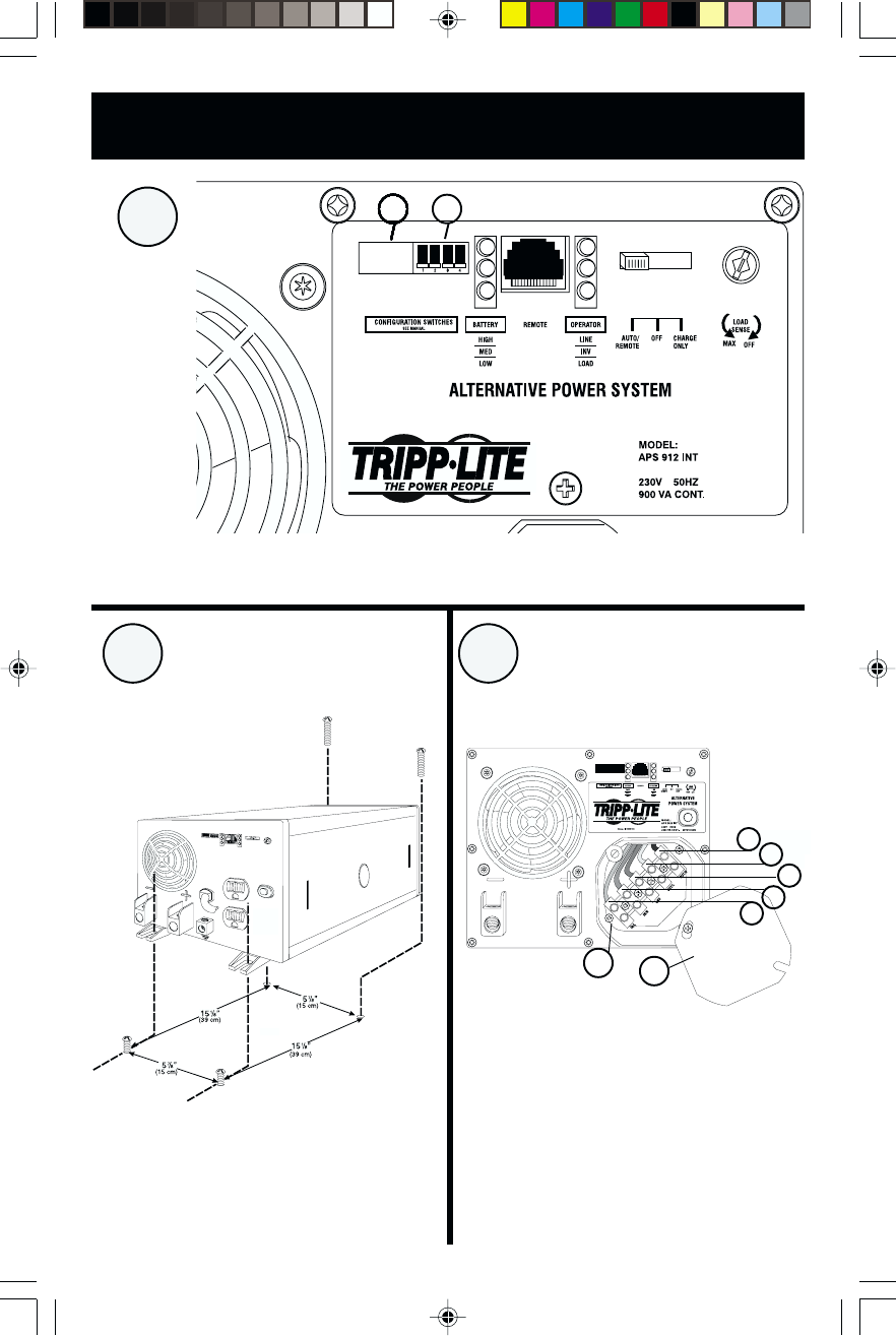
Diagrams/Esquemas
3
1
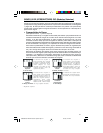
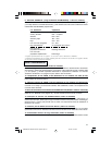
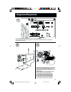
See "Configuration", pg. 5. 1.1 is DIP Switch Group A. 1.2 is DIP Switch Group B.
Refiérase a la sección “Configuración”, página 20. 1.1 representa el Grupo A de Interruptores DIP. 1.2 representa el
Grupo B de Interruptores DIP
1.11.2
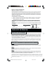
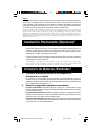
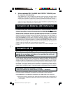
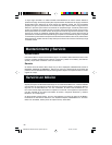
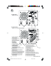
See Hardwire Electrical Connections, pg. 9. 3.1 is the cover
plate, 3.2 is the five-position terminal strip, 3.3 is the output
neutral (white), 3.4 is the output hot (black), 3.5 is the
ground (green), 3.6 is the input neutral (blue) and 3.7 is the
input hot (brown).
Refiérase a la sección “Conexiones Eléctricas Directas al
Circuito”, página 24. 3.1 representa la cubierta;
3.2 representa la barra de terminales de 5 posiciones;
3.3 representa la terminal neutra de salida (blanca);
3.4 representa la terminal positiva de salida (negra);
3.5 representa la terminal de conexión a tierra (verde);
3.6 representa la terminal neutra de entrada (azul) y
3.7 representa la terminal positiva de entrada (café).
1.21.21.21.21.21.21.21.21.21.21.21.21.21.2
3.2
3.1
3.7
3.6
3.3
3.4
3.5
9906058 230V APS MV-cabinet--Spanish.p65 3/21/00, 4:41 PM33