


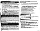
1.
Connect your APS's positive
DC
Terminal directly to a fuse.
UL recommends that you install a recognized UL component fuse block and fuse within 18
inches of the battery. The fuse's rating must equal or exceed the minimum fuse rating listed
in your APS model's specifications on pages 14 or
15.
2
Choose a battery configuration appropriate to your batteries.
Single Battery Connection: Refer to Diagram 4, page
33.
When using a single battery, its
voltage must be equal to the voltage of your APS's lnverter Nominal lnput Voltage (see specs.)
Parallel Battery Connection: Refer to Diagram
5,
page
33.
When using multiple batteries in
parallel, each battery's voltage must be equal to
the
voltage of your APS's Inverter Nominal
lnput Voltage (see specs.)
Series Battery Connection: Refer to Diagram
6,
page
33.
When using multiple batteries in
series, all batteries must be equal in voltage and amp hour capacity, and the sum of their
voltages must be equal
tothe voltage of your APS's lnverter Nominal lnput Voltage (see specs.)
"
Use the SHORTEST and HEAVIEST
GAUGE
battery cabling.
Use #4 cabling for DC cable lengths up to 10 feet. Use #2 cabling for lengths up to
16
ft.
Shorter
and heavier gauge cabling limits DC voltage drop and allows for maximum transfer of current.'
'APS
models ore ropublc of delivering a much higher worruge ourpur for brief periods oj rime. Wiring should be
configured
ro Wc rhis brief high-currcnr druw. Though your
APS
is u high-eficiency conveners of elecrriciry,
irs
mted
owpw
copmiry
u
limircd by rhc length
ond
gauge of rhc wires m'ng from rhc boncry ro rhc
APS.
.,.'
APS systems may permanently mounted in a car, truck or boat and connected to draw power
from the vehicle's battery. Note: do not connect
a
24V
or
36V
APS
to a vehicle's battery. There
are two main ways to make this sort of vehicular battery connection. Choose the Basic Connection
if
you are running light hand tools or other small appliances for a brief period of time
(see
Diagram
7,
p.
34).
Choose the Advanced Connection if you are using your APS to power heavy loads for
extended periods of time (see Diagram
8,
p.
34).
The Advanced Connection incorporates a batteq
isolator and separate battery system to provide battery power to your APS while preventing it from
draining your vehicle's battery. Note: Depending on your application, you may require more than
12V
Deep Cycle Battery.
h:
Nsw
opd
pur
APS
fmm
an
&mator
wichoul
a
baifq
connecrcd
as
shown
in
Diu#mx
7
or
8,
p.
34
Pzfore AC connection, match the power requirements of your
equipment with the power output of your APS to avoid overload.
When figuring the power requirements of your equipment, do not confuse 'continuous' power
ratings with 'peak' power ratings. Electric motors require more power to turn on ('peak power')
than
they require to wn continuously. 'Peak' power ratings are usually
2
to
5
times 'Continuous'
ratings. Most electric motors require 'peak power' only when they are
turned on. The elecbic motors
in equipment such as refrigerators and sump pumps, however. constantly
turn
on and off according
to
demand. These motors require 'peak power' at multiple, unpredictable times during their operation.
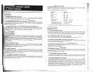
8
Hardwired Electrical Connections
(All hardwire models)
Refer to the electrical schematic. Diagram
3
on page
32,
for proper electrical connection of hardwired
APS models. Consult a qualified electrician and follow all applicable electrical codes and requirements.
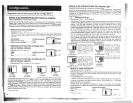
1) Loosen screws and remove cover plate from your APS's Hardwire AC electrical box. Remove
the knockout covers closest to the desired electrical source and to your equipment.
2) Thread your wires through strain reliefs and through the knockouts.
3)
Connect both input and output ground wires to the ground (green) terminal.
4)
Connect the incoming hot wire to the input hot (brown) terminal.
5)
Connect the incoming neutral wire to the input neutral (blue) terminal.
6)
Connect the outgoing hot wire to the output hot (black) terminal.
7)
Connect the outgoing neutral wire to the output neutral (white) terminal.
8)
Tighten and affix strain reliefs. Replace cover plate and tighten screws.
AC lnput Electrical Connection
(All corded models)
Plug the line cord into an outlet providing 120V AC,
60
Hz. power. Make sure that the circuit you
connect your APS to has adequate overload protection, such as a circuit breaker or a fuse.
AC
Output Electrical Connection
(All corded models)
Simply plug your equipment into the unit's AC receptacles.
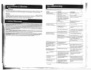
Set Operating Mode Switch
1
Switch to 'AUTOIREMOTE" when you are using connected equipment. ADVANTAGE:
Provides battery backup power during blackouts or brownouts.
Note: When the swltch is in the
"AUTOIREMOTE'
position, you can operate a user-
supplied swltch to transfer between battery-backup and chargeonly modes.
(See
Remote Connector description on page
10.)
Switch to "CHARGE ONLY" when you are not using connected equipment.
(WARNING! APS will not provide battery backup!) ADVANTAGES: A) Continues to charge battery
when power is present, and
8) Turns OFF the APSs inverter, preventing battery drain during
blackouts or brownouts.
Switch to "OFF to completely turn off the APS and connected equipment or to reset the APS
after it has shut down due to overload or oveheating.