


5
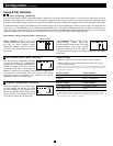
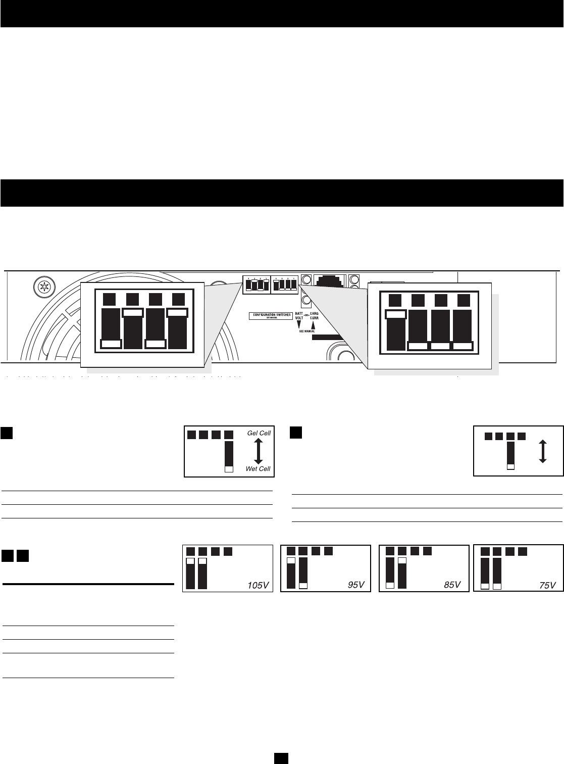
Select Battery Type—REQUIRED
CAUTION: The Battery Type DIP Switch setting must
match the type of batteries you connect, or your batteries
may be degraded or damaged over an extended period of
time. See “Battery Selection,” for more information.
Battery Type Switch Position
Gel Cell (Sealed) Battery Up
Wet Cell (Vented) Battery Down (factory setting)
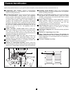
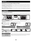
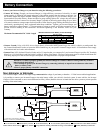
INPUT C/B 10A
OUTPUT C/B 12A
B4 B3 B2 B1
A4 A3 A2 A1
Group B Dip Switches
Group A Dip Switches
Group A DIP Switches
Using a small tool, configure your Inverter/Charger by setting the four Group A DIP Switches (located on the front panel of your unit; see
diagram) as follows:
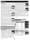
A1
Operation
(continued)
Resetting Your Inverter/Charger to Restore AC Power
Your Inverter/Charger may cease supplying AC power or DC charging power in order to protect itself from overload or to protect your
electrical system. To restore normal functioning:
Overload Reset: Switch operating mode switch to “DC OFF” and remove some of the connected electrical load (ie: turn off some of the
AC devices drawing power which may have caused the overload of the unit). Wait one minute, then switch operating mode switch back to
either “AUTO/REMOTE” or “CHARGE ONLY.”
Output Circuit Breaker Reset: Alternatively, check output circuit breaker on the unit's front panel. If tripped, remove a portion of the
electrical load, wait one minute to allow components to cool, then reset the circuit breaker. See the Troubleshooting section for additional
possible reasons why AC output may be absent.
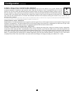
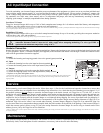
Select Low AC Input Voltage
Point for Switching to Battery—
OPTIONAL*
Switch
Voltage Position
105V #A4 Up & #A3 Up
95V #A4 Up & #A3 Down
85V #A4 Down & #A3 Up
75V #A4 Down & #A3 Down
(factory setting)
A1A2A3A4
A1A2A3A4
A1A2A3A4
A1A2A3A4
A3
A4
* Most of your connected appliances and equipment will perform adequately when your Inverter/Charger’s Low AC Voltage Input Point
(DIP Switches #3 and #4 of Group A are set to 95V. However, if the unit frequently switches to battery power due to momentary low
line voltage swings that would have little effect on equipment operation, you may wish to adjust these settings. By decreasing the Low
AC Voltage Point, you will reduce the number of times your unit switches to battery due to voltage swings.
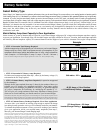
Configuration
Set Configuration DIP Switches
Using a small tool, set the Configuration DIP Switches (located on the front panel, see diagram) to optimize Inverter/Charger operation
depending on your application.
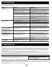
Charger Inhibit
Function Switch Position
Charger Inhibited Up
Charger Enabled Down (factory setting)
A2
A1A2A3A4
A1A2A3A4
Charger
Inhibite
d
Charger
Enabled