


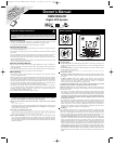
AC Outlets: All outlets provide connected equipment with AC line power (backed by surge
protection and line noise filtering) during normal operation. Automatic voltage regulation
continually corrects brownout (low voltage) and high voltage conditions without using battery
power. All outlets provide battery power during blackouts and severe brownout or severe high
voltage conditions.
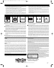
USB and RS-232 Communication Ports: These ports can connect the UPS to audio/video
control systems, media center PCs or music servers for automatic file saves and unattended
shutdown in the event of a power failure. Use with Tripp Lite's PowerAlert Software (available
as a FREE download at www.tripplite.com) and appropriate USB or DB9 cable. Note: This
connection is optional. The UPS will work properly without this connection. Also Note: This
UPS System provides basic communication compatibility with most integrated Windows
®
,
Macintosh
®
and Linux
®
power management applications.
Tel/DSL/Network Line Surge Protection Jacks: The UPS has jacks that protect against
surges on a single phone, fax, modem or Ethernet network line. Using appropriate telephone or
network cords, connect the wall jack to the UPS jack marked “IN.” Connect the equipment to
the UPS jack marked “OUT.” Make sure the equipment connected to the jacks is also protected
against surges on the AC line. Connecting equipment to these jacks is optional. The UPS will
work properly without this connection. Not compatible with PoE (Power Over Ethernet)
applications.
Coaxial Protection Jacks: Gold coaxial connectors protect components by stopping surges on
DSS satellite, cable or antenna lines. Connect a coaxial cable from the wall jack directly to the
coaxial jack labeled “IN.” Connect a coaxial cable from the coaxial jack labeled “OUT”
directly to the device to be protected. The UPS system must always be the first item connected
in line from the coaxial wall jack. The UPS system must be plugged into a 3-wire grounded AC
outlet for coaxial line surge protection to work. Make sure cables connected to satellite dishes,
antennas, etc. are also grounded.
Power Sensitivity Dial: This dial is normally set fully counterclockwise, which enables the
UPS to protect against waveform distortions in its AC input. When such distortion occurs, the
UPS will normally switch to providing PWM sinewave power from its battery reserves for as
long as the distortion is present. In some areas with poor utility power or where the input power
comes from a backup generator, frequent brownouts and/or chronic waveform distortion could
cause the UPS to switch to battery too often, draining its battery reserves. Experimenting with
different settings for this dial may reduce how often your UPS switches to battery due to
waveform distortion or brownouts. As the dial is turned clockwise, the UPS becomes more
tolerant of variations in its input power's AC waveform. NOTE: The further the dial is adjusted
clockwise, the greater the degree of waveform distortion the UPS will allow to pass to
connected equipment. When experimenting with different settings for this dial, operate
connected equipment in a safe test mode so that the effect on the equipment of any waveform
distortions in the UPS's output can be evaluated without disrupting critical operations. The
experiment should last long enough to assure that all expected line conditions are encountered.
Battery Replacement: Under normal conditions, the original battery in the UPS will last
several years. Battery replacement should be performed only by qualified service personnel.
During battery replacement, qualified service personnel should refer to
“Battery Warnings” in the Safety section. Tripp Lite offers a complete line of replacement batteries
at www.tripplite.com/support/battery/index.cfm.
RS-232 Port
USB Port
5a
Tel/DSL/Network Jacks
AC Outlets
4
5b
6
Power Sensitivity Dial
8
Coaxial Protection Jacks
7
Basic Operation
(Front Panel)
continued
Basic Operation
(Rear Panel)
Storage
To avoid battery drain, all connected equipment should be turned off and disconnected from the
UPS. Press and hold the ON/OFF button for one second. The UPS will be completely turned off
(deactivated), and will be ready for storage. If the UPS will be stored for an extended period, fully
recharge the UPS batteries every three months. Plug the UPS into a live AC outlet, turn it on by
pressing and holding the ON/OFF button for one second, and allow the batteries to recharge for 4
to 6 hours. If the UPS batteries are discharged for a long period of time, they will suffer a
permanent loss of capacity.
Service
Before returning the UPS for service, follow these steps: 1. Review the installation and operation
instructions in this manual to ensure that the service problem does not originate from a misreading
of the instructions. 2. If the problem continues, do not contact or return the UPS to the dealer.
Instead, call Tripp Lite at (773) 869-1233. A service technician will ask for the UPS's model
number, serial number and purchase date and will attempt to correct the problem over the phone.
3. If the problem requires service, the technician will issue a Returned Material Authorization
(RMA) number, which is required for service. If you require packaging, the technician can
arrange to send you proper packaging. Securely pack the UPS to avoid damage during shipping.
Do not use Styrofoam beads for packaging. Any damages (direct, indirect, special, incidental or
consequential) to the UPS incurred during shipment to Tripp Lite or an authorized Tripp Lite
service center is not covered under warranty. UPS Systems shipped to Tripp Lite or an authorized
Tripp Lite service center must have transportation charges prepaid. Mark the RMA number on the
outside of the package. If the UPS System is within the 2-year warranty period, enclose a copy of
the sales receipt. Return the UPS for service using an insured carrier to the address supplied by the
Tripp Lite service technician.
Visit www.tripplite.com/warranty today to register the warranty for your new Tripp Lite product.
You'll be automatically entered into a drawing for a chance to win a FREE Tripp Lite product! *
* No purchase necessary. Void where prohibited. Some restrictions apply. See website for details.
3c) “AVR” (Automatic Voltage Regulation) Icon: This icon will illuminate whenever the
UPS is automatically correcting low AC line voltage without depleting battery power. This
is a normal, automatic operation of the UPS, and no action is required.
3d) “REPLACE” (Battery Recharge/Replace) Icon: This icon will illuminate and an
alarm will sound after a self-test to indicate the UPS battery needs to be recharged or
replaced. Allow the UPS to recharge continuously for 12 hours, and repeat the self-test. If the
icon continues to illuminate, contact Tripp Lite for service. Battery replacement should only
be performed by qualified service personnel. If the UPS requires battery replacement, Tripp
Lite offers a complete line of replacement batteries at www.tripplite.com.
3e) “ON BAT” (On Battery) Icon: During a severe brownout or blackout, this icon
illuminates and an alarm sounds (4 short beeps followed by a pause) to indicate the UPS is
operating from its internal batteries. Monitor the “Battery Capacity” Meter to determine the
approximate battery charge level available to support equipment. During a prolonged
brownout or blackout, the alarm will sound continuously (and the “BATTERY CAPACITY”
Meter will show one 20% capacity segment shaded) to indicate the batteries are nearly out
of power; save files and shut down equipment immediately.
3f) “FAULT” Icon: This icon will illuminate and an alarm will sound after a self-test to
indicate the outlets are overloaded. To clear the overload, unplug some equipment from the
outlets and run the self-test repeatedly until the icon is no longer illuminated and the alarm
is no longer sounding.
CAUTION! Any overload that is not corrected by the user immediately following a self-
test may cause the UPS to shut down and cease supplying output power in the event of
a blackout or brownout.
4
6
7
5
8
WARRANTY REGISTRATION
FCC Part 68 Notice (United States Only)
If your Modem/Fax Protection causes harm to the telephone network, the telephone company may temporarily discontinue your service. If possible, they
will notify you in advance. If advance notice isn't practical, you will be notified as soon as possible. You will be advised of your right to file a complaint
with the FCC. Your telephone company may make changes in its facilities, equipment, operations or procedures that could affect the proper operation
of your equipment. If it does, you will be given advance notice to give you an opportunity to maintain uninterrupted service. If you experience trouble with
this equipment's Modem/Fax Protection, please call Tripp Lite Technical Support at (773) 869-1234 for repair/warranty information. The telephone
company may ask you to disconnect this equipment from the network until the problem has been corrected or you are sure the equipment is not
malfunctioning. There are no repairs that can be made by the customer to the Modem/Fax Protection. This equipment may not be used on coin service
provided by the telephone company. Connection to party lines is subject to state tariffs. (Contact your state public utility commission or corporation
commission for information.)
FCC Radio/TV Interference Notice (U.S. only)
Note: This equipment has been tested and found to comply with the limits for a Class B digital device, pursuant to Part 15 of the FCC Rules. These limits
are designed to provide reasonable protection against harmful interference in a residential installation. This equipment generates, uses and can radiate
radio frequency energy, and if not installed and used in accordance with the instruction manual, may cause interference to radio communications.
However, there is no guarantee that interference will not occur in a particular installation. If this equipment does cause harmful interference to radio or
television reception, which can be determined by turning the equipment off and on, the user is encouraged to try to correct the interference using one or
more of the following measures: reorient or relocate the receiving antenna; increase the separation between the equipment and the receiver; connect
the equipment into an outlet on a circuit different from that which the receiver is connected; consult the dealer or an experienced radio/television
technician for help. The user must use shielded cables and connectors with this product. Any changes or modifications to this product not expressly
approved by the party responsible for compliance could void the user’s authority to operate the equipment. This device complies with part 15 of the FCC
rules. Operation is subject to the following 2 conditions: (1) This device may not cause harmful interference, and (2) This device must accept any
interference received, including interference that may cause undesired operation.
Equipment Attachment Limitations (models with the Industry Canada label in Canada only)
NOTICE: The Industry Canada label identifies certified equipment. This certification means that the equipment meets the telecommunications network
protective, operational and safety requirements as prescribed in the appropriate Terminal Equipment Technical Requirements Document(s). The
Department does not guarantee the equipment will operate to the user’s satisfaction.
Before installing this equipment, users should ensure that it is permissible to be connected to the facilities of the local telecommunications company. The
equipment must also be installed using an acceptable method of connection. The customer should be aware that the compliance with the above
conditions might not prevent degradation of service in some situations.
Repairs to certified equipment should be coordinated by a representative designated by the supplier. Any repairs or alterations made by the user to this
equipment, or equipment malfunctions, may give the telecommunications company cause to request the user to disconnect the equipment.
Users should ensure for their own protection that the electrical ground connections of the power utility, telephone lines and internal metallic water pipe
system, if present, are connected together. This precaution may be particularly important in rural areas. Caution: Users should not attempt to make
connections themselves, but should contact the appropriate electric inspection authority, or electrician, as appropriate.
Note on Labeling
Two symbols are used on the label.
V~ : AC Voltage
V : DC Voltage
Regulatory Compliance Identification Numbers
For the purpose of regulatory compliance certifications and identifica-
tion, your Tripp Lite product has been assigned a unique series number.
The series number can be found on the product nameplate label, along
with all required approval markings and information. When requesting
compliance information for this product, always refer to the series num-
ber. The series number should not be confused with the marking name
or model number of the product.
This product designed and engineered in the USA.
1111 W. 35th Street • Chicago, IL 60609 USA
(773) 869-1234 • www.tripplite.com
Copyright © 2006 Tripp Lite. All rights reserved. All trademarks are the property of their respective owners.
200605055
93-2560
200605055 93-2560 OMNI1300LCD OM.qxd 5/8/2006 5:24 PM Page 2