


Installation
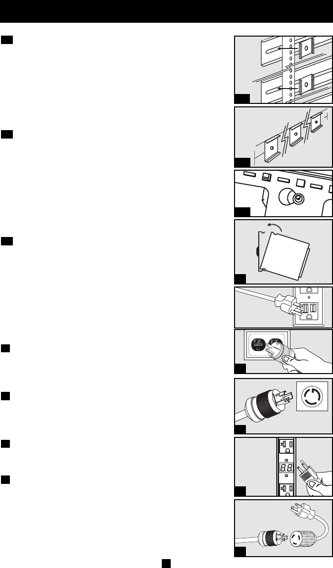
Zero U Rack Configuration. Attach the three mounting
clips supplied with the PDU to the rack enclosure using the
included hardware. The mounting clips should be attached
along a vertical plane at equidistant points which roughly
correspond to the center and ends of the PDU. The exact
mounting configuration may vary depending on the rack and
enclosure. If possible, use pre-existing mounting points within
the enclosure.
Wall or Under-Counter Configuration. Attach the three
mounting clips supplied with the PDU to a wall or similar flat,
secure surface using the included hardware. The mounting
clips should be attached along a vertical or horizontal plane at
equidistant points which roughly correspond to the center and
ends of the PDU. If possible, use pre-existing mounting
points. WARNING: Do not attempt to mount the PDU with
the outlets facing downward; the mounting clips are not
designed to support the weight of the PDU in that manner.
Zero U Rack Configuration (Mounting Buttons).
Attach the included mounting buttons to the PDU. Position the
PDU as desired in the rack enclosure, align the buttons with
the rack mounting slots, and slide the PDU into position.
Note: Regardless of configuration, the user must determine
the fitness of hardware and procedures before mounting. The
PDU and included hardware are designed for common rack
and rack enclosure types and may not be appropriate for all
applications.
Attach the PDU to the mounting clips. Using an assistant,
place a rear corner of the PDU at an inside edge of the
mounting clips, pivot the PDU toward the alternate inside
edge and snap into place.
Attach the input plug of the PDU to a grounded outlet.
Insert the plug directly into a grounded outlet that does not
share a circuit with a heavy electrical load (such as an air
conditioner or refrigerator).
Attach equipment to the PDU. Do not exceed the load
rating of the PDU. The total electrical current used by the
PDU will be displayed on the digital meter in amperes.
Optional Installation (Model PDUMV20 Only). The
PDU includes an adapter that converts the L5-20P input plug
to a 5-20P input plug. The adapter is optional; the PDU will
work properly without connecting the adapter.
5
4
3
2
1C
1B
1A
2
1B
1A
3
4
5
2
PDUMV15 and
PDUV15
PDUMV20
PDUMV20 only
1C
3
PDUV20
200801266 93-2781 PDUMV20 om.qxd 2/14/2008 11:30 AM Page 2