


7
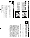
USB Port: The USB port connects your UPS to any USB workstation
or server. Using this port, your UPS can communicate line-fail and
low-battery status to your computer. Use with Tripp Lite software and
any USB cable to automatically save open files and shut down equip-
ment during a blackout. Contact Tripp Lite Customer Support or con-
sult your power protection software manual for more information.
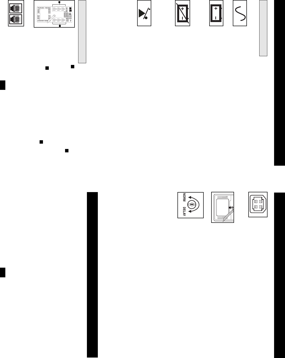
Battery Replacement Door: Under normal conditions, the original bat-
tery in your UPS will last several years. Refer to “Battery Warnings” in
the Safety section on page 2. Tripp Lite offers a complete line of UPS
System Replacement Battery Cartridges (R.B.C.). Visit Tripp Lite on
the Web at www.tripplite.com/support/battery/index.cfm to locate the
specific replacement battery for your UPS.
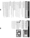
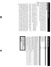
Power Sensitivity/Lowline Adjustment: This dial is normally set fully
counterclockwise, which enables the UPS to protect against waveform
distortions in its AC input. When such distortion occurs, the UPS will
normally switch to providing PWM sinewave power from its battery
reserves for as long as the distortion is present. In some areas with poor
utility power or where the UPS’s input power comes from a backup
generator, frequent brownouts and/or chronic waveform distortion
could cause the UPS to switch to battery too often, draining its battery
reserves. You may be able to reduce how often your UPS switches to
battery due to waveform distortion or brownouts by experimenting with dif-
ferent settings for this dial. As the dial is turned clockwise, the UPS
becomes more tolerant of variations in its input power’s AC wave-
form and reduces the voltage point at which it switches to battery.
NOTE: The further the dial is adjusted clockwise, the greater the degree
of waveform distortion and the lower the input voltage the UPS will
allow to pass to connected equipment. When experimenting with dif-
ferent settings for this dial, operate connected equipment in a safe test
mode so that the effect on the equipment of any waveform distortions in
the UPS’s output can be evaluated without disrupting critical operations. The
experiment should last long enough to assure that all expected line con-
ditions are encountered.
Basic Operation
continued
Storage
All connected equipment should be turned off, then disconnected from the UPS to avoid battery
drain. Unplug the UPS from the wall outlet; then press and hold the ON/OFF button for one second.
The UPS will be completely “OFF” (deactivated). Your UPS is now ready for storage. If you
plan on storing your UPS for an extended period of time, fully recharge the UPS batteries once
every three months by plugging the UPS into a live AC outlet and letting the UPS charge for 4
to 6 hours. If you leave your UPS batteries discharged for an extended period of time, they will
suffer a permanent loss of capacity.
Storage & Service
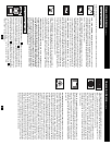
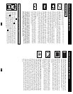
All Indicator Light descriptions apply when the UPS is plugged into an AC outlet and turned on.
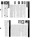
“LINE POWER” LED: this green LED lights continuously to indicate
that the UPS is ON and supplying your equipment with AC power from a
utility source. The LED flashes to remind you that you have used the
ON/OFF button to place the UPS in “Charge-Only” mode.
“BATTERY POWER” LED: this yellow LED flashes and an alarm
sounds (4 short beeps followed by a pause) to indicate the UPS is operating
from its internal batteries. During a prolonged brownout or blackout, this
LED and the “REPLACE BATTERY” LED will light continuously and an
alarm will sound continuously to indicate the UPS's batteries are nearly out
of power; you should save files and shut down your equipment immediately.
“REPLACE BATTERY” LED: this red LED lights continuously and an
alarm sounds after a self-test to indicate the UPS batteries need to be
recharged or replaced. Allow the UPS to recharge continuously for 12
hours, and repeat the self-test. If the LED remains lit, contact Tripp Lite for
service. If your UPS requires battery replacement, visit
www.tripplite.com/support/battery/index.cfm to locate the specific Tripp Lite
replacement battery for your UPS.
“OVERLOAD” LED: this red LED lights continuously and an alarm
sounds after a self-test to indicate the battery-supported outlets are overloaded.
To clear the overload, unplug some of your equipment from the battery-
supported outlets and run the self-test repeatedly until the LED is no longer
lit and the alarm is no longer sounding.
CAUTION! Any overload that is not corrected by the user immediately
following a self-test may cause the UPS to shut down and cease supplying
output power in the event of a blackout or brownout. An alarm will
sound continuously prior to shut down. The OVERLOAD LED will
light continuously just prior to and immediately after shut down.
Clear the overload in the same manner as described in the paragraph
above.
6
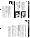
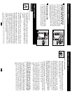
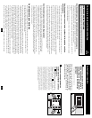
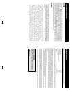
AC Outlets: the outlets will provide battery backup and surge protection;
plug your computer, monitor and other critical devices here. The outlets
will provide surge protection only; plug your printer and other non-essential
devices here. Your UPS is designed to only support computer equipment.
You will overload the UPS if the total VAratings for all the equipment you
connect to the outlets exceeds the UPS’s Output Capacity (see
Specifications). If you are unsure if you have overloaded the outlets, run
a self-test (see “MUTE/TEST” Button description).
Telephone/Network Protection Jacks: These jacks protect your equipment
against surges over a telephone or data line. Connecting your equipment
to these jacks is optional. Your UPS will work properly without this connection.
A
A
B
A
NORM DELAY
Basic Operation
continued
Other UPS Features
Indicator Lights
B
A