


7
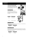
UPS LOCATION
Move your UPS over short distances using its wheels. Stabilize the UPS by releasing the
stabilizers on each side of the unit. NOTE: Do not stack the UPS Systems or external
battery packs.
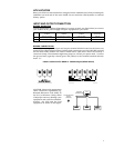
INPUT AND OUTPUT CONNECTION
WIRING SELECTION
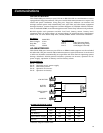
Choose appropriate cabling (depending on current carried; see chart below) to connect
your UPS to an AC power supply and your equipment to your UPS:
MODEL RATED INPUT RATED OUTPUT RATED OUTPUT OUTPUT
CURRENT CURRENT CURRENT PROTECTION
208/240 1Ø 3 Wire 120-208/240V 1Ø 3 Wire 120V 1Ø 3 Wire CIRCUIT
SU6K 30A 8 AWG (8mm
2
/60
o
C) 30A 8 AWG (8mm
2
/60
o
C) 2 x 32A 6 AWG (14mm
2
/60
o
C) 32A
SU10K 50A 6 AWG (14mm
2
/60
o
C) 50A 6 AWG (14mm
2
/60
o
C) 2 x 50A 4 AWG (22mm
2
/60
o
C) 63A
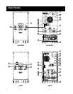
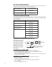
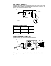
WIRING CONNECTIONS
Connect your wiring to the input and output terminal blocks located on the lower rear
panel of your UPS (see figure below). Before cable connection, turn the UPS OFF and pull
out the fuse holder. Ensure the cable is fitted with a cable sleeve and is secured by a
connector clamp. The minimum tightening torque is 35 lbs. per square inch. Connect
the ground wire (typically colored green and yellow) to the terminal marked with the
letter "G."
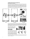
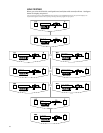
Cable Connection for 6kVA or 10kVA Output (6kVA shown)
CAUTION: Observe the appropriate
cable connection regulations [e.g.
National Electrical Code (NEC) in
the U.S.] at all times. Using cables
of improper size may damage your
equipment and cause fire hazards.
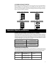
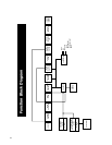
Ground the UPS and the load
equipment as shown in the figure.
UPS
LOAD 1
LOAD 2
LOAD 3
TO THE BUILDING
EARTH
(GROUND)
GROUND
CONNECTION