


5
Important Safety InstructionsOptional Installation
4
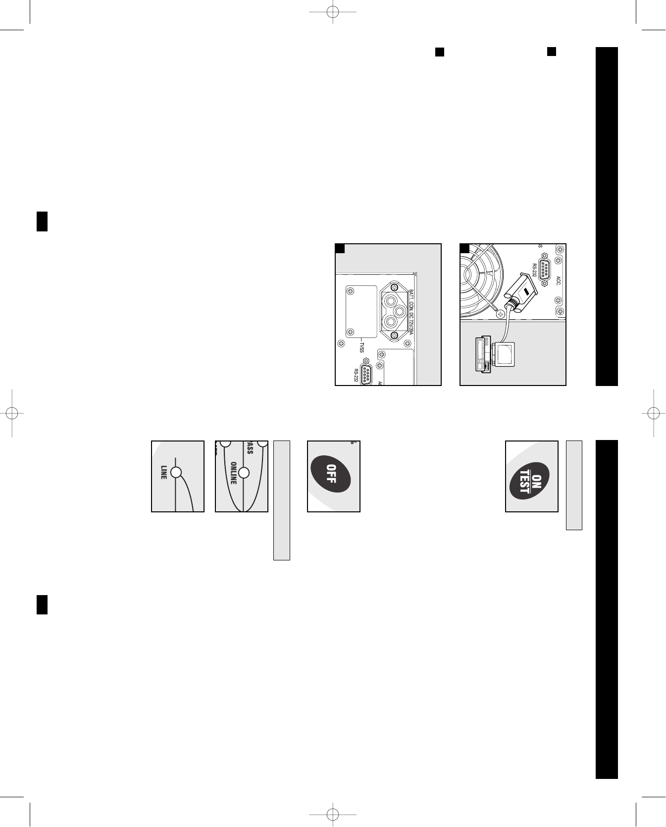
The connections are optional. Your UPS will function properly
without these connections.
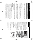
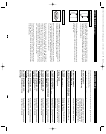
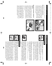
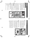
Serial Port Connection
Using the serial cable provided, connect the
serial port on your computer to the serial port
of your UPS. Install on your computer the
PowerAlert UPS monitoring software pro-
gram (included on CD-ROM) appropriate for
your operating system. See Communications
in the Basic Operation section of this manual
to determine how to monitor and manage your
UPS using this port.
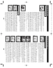
External Battery Pack Connection
Check to ensure that the external batteries you
are connecting match the voltage listed on
your UPS's battery connector. Plug either end
of the battery connection cable (supplied with
the battery pack) into the UPS’s External
Battery Connector and the other end into the
Battery Output Connector on the rear panel of
the external battery pack. Since your UPS has
internal batteries, external batteries are only
needed to extend runtime. Adding external
batteries will increase recharge time as well as
runtime. Make sure that each end of the cable is
fully inserted into its connector. Several small
sparks may result during battery connection;
this is normal.
1
1
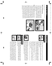
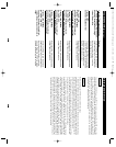
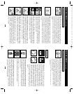
SU1000T shown
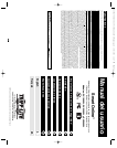
Basic Operation
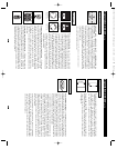
Front Panel Switches
“ON/TEST” Switch: This switch controls four separate UPS functions:
UPS Power ON: To turn the UPS on, press this switch, hold it for
several seconds until you hear a beep, then release it. The “ON LINE”
LED will illuminate.
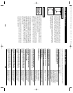
UPS Self-Test: During normal on-line operation, press this switch
and hold it until you hear a beep. This initiates a 10-second self-test
of the battery. The UPS will shift to battery power (the “ON BATT”
and “BATT ACTIVE METER” LEDs will illuminate) for ten seconds.
Alarm Silence: To silence the UPS “on-battery” alarm, press this
switch and hold it until you hear a beep.
UPS Cold Start: To use your UPS as a stand-alone power source
when AC power is unavailable (i.e. during a blackout), press this
switch and hold it until you hear a beep. The UPS will then provide bat-
tery power to its outlets.*
* The “ON BATT” Indicator Light will be illuminated since your UPS will be operating
from battery power.
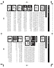
“OFF” Switch: This switch turns power OFF at the UPS receptacles.
Press this switch, hold it until you hear a beep, then release it. The
UPS will continue charging and the fan will continue to cool internal
components even after you turn the UPS receptacles off. To turn the
UPS OFF completely, including the charger, disconnect the UPS’s
power cord after pressing the “OFF” switch.
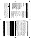
“ON LINE” LED: This green light will be lit when the UPS is in normal
on-line operation (filtering and resynthesizing incoming AC line voltage
to provide pure sine wave output). When this light is illuminated, you
can monitor the load level of your UPS on the “LOAD ACTIVE
METER” LEDs.
“LINE” LED: This green light will be lit when the utility-supplied
AC line voltage at your wall outlet is nominal. It will flash if the line
voltage or frequency is outside the nominal range (either too low or
too high). No action is required on your part when the LED flashes;
the UPS continuously and automatically filters AC line power to pro-
vide your equipment with pure sine wave AC power, regardless of
brownout or overvoltage conditions. If this light is off, then AC line
voltage is not present (blackout) or is at an extremely high voltage.
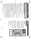
Front Panel Indicator Lights
2
2
SU2200XL shown
SU2200XL shown
200308027 SU1000-2200-3000XL Owner’s Manual.qxd 10/6/2003 12:17 PM Page 4