


1
5
9
3
7
11
2
6
10
4
8
12
13
14
OUTPUT
DRY CONTACT
58
11 – Communications (continued)
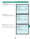
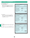
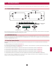
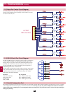
11-9 Output Dry Contact Circuit Diagram
The UPS system has six dry contact output connections. These
contacts can be normally open or normally closed. Contacts are rated
for 250V AC/28V DC; 8A.
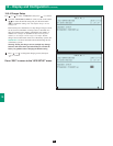
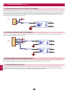
11-10 RS-232 Serial Port Circuit Diagram
The RS-232 DB9 serial port connects the UPS system to a workstation
or server (cable included). By communicating with the UPS system
through this port, Tripp Lite’s PowerAlert UPS management software
(included) can monitor and control the UPS system. PowerAlert also
serves as an SNMP proxy allowing the UPS system to appear as an
SNMP-manageable device on the network.
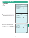
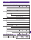
RS-232 signals and operations include: load level, battery status, battery
level, operation mode, AC input voltage, AC output voltage, AC input
frequency, internal temperature, set shut-down delay time, enable/
disable alarm and remote shutdown.
Hardware
Baud Rate: 2400 BPS
Data Length: 8 bits
Stop Bit: 1 bit
Parity: NONE
Pin Assignment
Pin 2: TXD (Transmit Data)
Pin 3: RXD (Receive Data)
Pin 5: GND (Signal Ground)
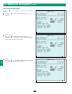
11-11 Parallel Configuration Port
The parallel configuration port allows the UPS system to be connected to another UPS system of identical type and capacity for use in a parallel
(1+1) configuration for increased capacity or increased fault-tolerance. Warning: Use only the parallel configuration cable that is included
with the UPS system. Attempting to use an incompatible cable may damage the UPS systems and create a serious risk of personal injury
and property damage.