


SPECIFICATIONS
Product offerings and specifications are subject to change without notice. Actual products may vary from photos. Not all products include all features. Availability varies
by region; contact your sales representative. Certain product names mentioned herein may be trade names and/or registered trademarks of other companies.
© 2008 Tyco International Ltd. and its respective companies. All rights reserved. SH0146-DS-200810-R01-LT-EN
www.swhouse.com
(
*
) For plenum or underground applications, use Belden 89182 for one pair 22 AWG, 100 ohm 12.95 pf/ft.
Note: Control, supervised, and unsupervised input cables must be shielded for FCC Class B operation.
General
Dimensions (H x W) .....11.0 x 15.0 cm (4.3 x 5.9 in)
Environmental.......... 0° to 50° C (32° to 122° F); 5 to 85% relative
humidity, non-condensing
Power Input Voltage .....12 VDC +/- 10%
Tamper ...............Dedicated input for external tamper switch
Weight................0.23 kg (8 oz)
Regulatory ............ UL 294, UL 1076, FCC Part A
CE, EN 50133, ROHS
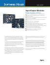
I8 Input Module
Power Requirements ....180 mA @ 12 VDC
Inputs ................Eight Class A supervised
LEDs per Input ......... Red (alarm), green (normal), and yellow
(supervision error)
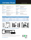
I8-CSI Input Module
Power Requirements ....80 mA @ 12 VDC
Inputs ................Eight Class A supervised, configurable via DIP switch
LEDs per Input ......... Red (alarm), green (normal) and yellow
(supervision error)
Circuits Supported ...... Single resistor: 1K, 5K, 10K
Double resistor: 1K, 5K, 10K,
1K/2K, 6.8K/18K, 200/10K
Unsupervised: NO, NC
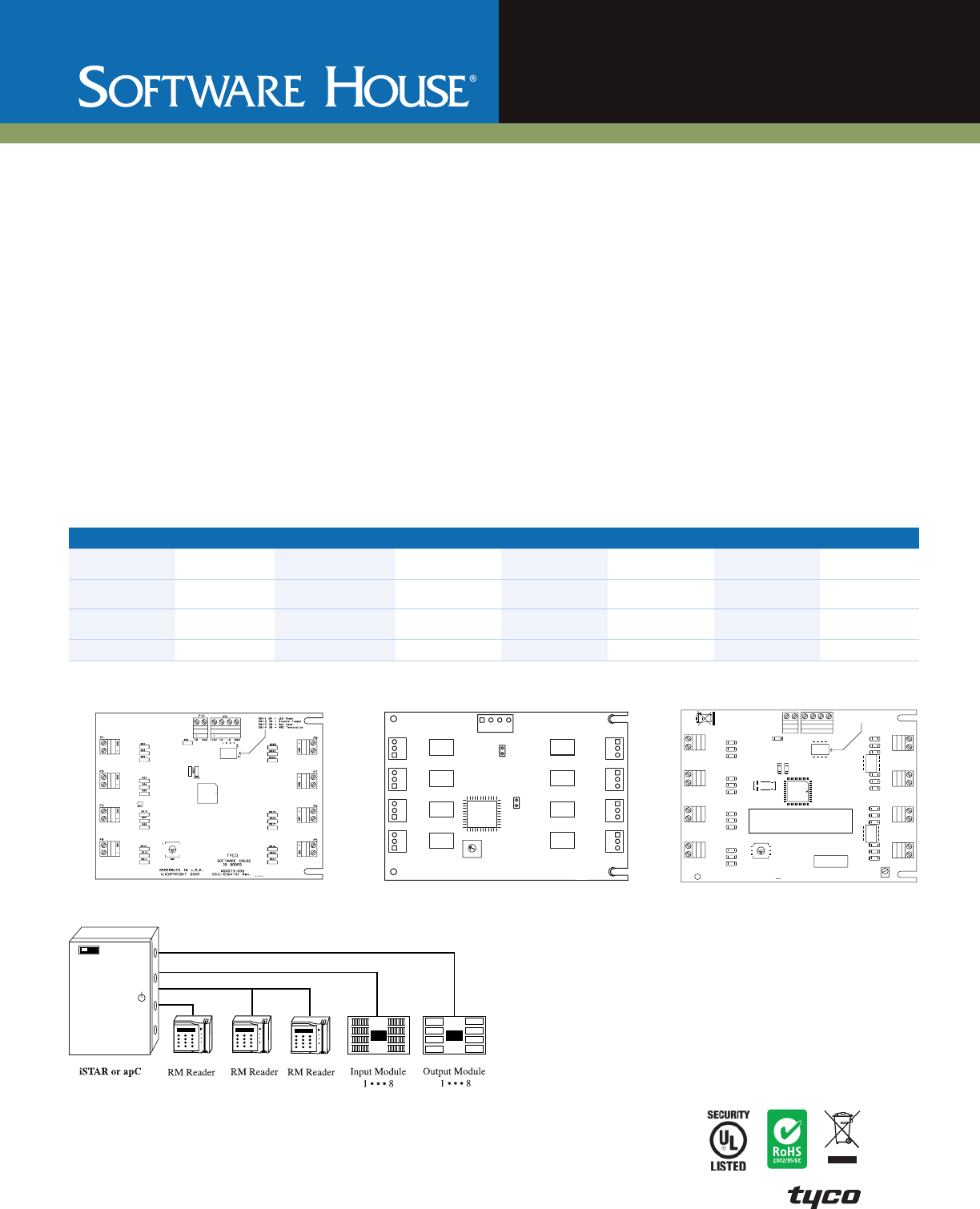
R8 Output Module
Power Requirements ....45 mA @ 12 VDC plus 32 mA per active relay
Outputs...............Eight Form C dry contact relays
LED per Output.........Red (relay active)
Relay Contact Ratings ... 30 VDC, 2.0 A resistive
30 VDC, 1.0 A inductive
125 VAC, 4.0 A
Optional Metal Enclosures with Tamper Switch
RM-DCM-CAN
Dimensions...........356 x 305 x 89 mm (14 x 12 x 3.5 in)
Capacity .............Up to four input or output modules
RM-CAN
Dimensions...........210 x 184 x 83 mm (8.25 x 7.25 x 3.25 in)
Capacity .............One input or output module
Model Numbers
AS0073-001 ...........I8 input module
AS0073-CSI ...........I8-CSI input module
AS0074-000 . . . . . . . . . . .R8 output module
RM-DCM-CAN .........Large metal enclosure with tamper switch
RM-CAN ..............Small metal enclosure with tamper switch
Wiring Summary
Signal From To Belden # Gauge # of Pairs Shielded Maximum Length
Comm
(two-wire RS485)
apC/iSTAR I8/R8 9841* 24 1 Yes
1,220 m
(4,000 ft)
Power apC/iSTAR I8/R8 9841* 24 1 No
Based on
voltage drop
Control Point R8 Strike, Siren, etc. 8442/8461 18 1 No
Based on
voltage drop
Supervised Input I8 REX or Door Contact 8442/8461 22/18 1 No 610 m (2,000 ft)
Wiring Configuration Diagram
I8 Input Module Configuration
R8 Output Module Configuration
0
1
2
3
F
E
D
C
B
A
4
5
6
7
8
9
1
SW1
4
SOFTWARE HOUSE
MADE IN USA
P9
P2
P3
P4
P8
P7
P6
P5
W1
TAMPER
INPUT
P1
R8 OUTPUT MODULE
AS-0074-000 REV.A
NO
NO
NO
NO
NO
NO
NO
NO
NC
NC
NC
NC
NC
NC
NC
NC
C
C
C
C
C
C
C
C
NOTE: All mounting holes are 1/8" dia.
Max. component height 1/2".
23
1
2
3
1
2
3
1
2
3
1
2
3
1
2
3
1
2
3
1
2
3
1
2
3
I8-CSI Input Module Configuration
P b
Pb-Fr ee
P5
INE 1
P6
INF 1
P7
ING 1
P8
INH 1
P10P9
GND GNDTS +D -D+12V
1
1
P4
IND 1
P3
INC 1
P2
INB 1
P1
INA 1
S1-1 ON = LED Power
S1-2 ON = Disable Tamper
S1-3 ON = Not Used
S1-4 ON = 485 Termination
DS4
DS25
DS3
DS2
DS27
Y1
DS26
DS1
DS24
DS23
DS22
S3
1 2 3 4
NO
DS21
DS20
DS7
DS6
DS5
DS10
DS9
DS8
DS13
DS12
DS11
S3
DS19
DS18
DS17
DS16
S2
1 2 34
ON
DS15
DS14
S2
S1
U3
FOR SWH STD 1K DUAL S2:3-4, S3:1-4 = OFF
SEE QUICKSTART DOC FOR OTHER SETTINGS
CYCLE POWER AFTER SETTING
1234
ON
S1
SW1
1
TYCO
SOFTWARE HOUSE
ASSEMBLED IN USA
C
COPYRIGHT 2007
"WARNING Damage may result from incorrectly
wiring power terminals, input and output lines, and
central-supervising station lines. Check all
connections before powering the unit."
0312–5008–01 Rev.
18–CSI BOARD
®
Input Rating P9
12VDC 125mA
Refer to Quick Start Installation Guide,
P/N UM-218, Rev B0, July 2008
Sample System Configuration: Combination Bus/Star Wiring Diagram