


19-2021 Rev E, 06/05/07
9
IMPORTANT
It is a requirement to incorporate the wire raceway covering to all exposed portions of
the wire raceway on the mounting sides of the Main Support where modules have been
mounted.
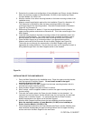
27. Identify, measure and record all spaces on the Main Support between Lamp Modules
and the Power Junction Module (see Figure 2b).
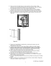
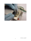
28. Place the bare wire/raceway cover onto a horizontal surface in an appropriate work
area. Mark off the dimensions corresponding to the gap dimensions recorded in step
7 onto the raceway cover sections. Make one cut through the cross-section of the
raceway cover for each space identified using a tool appropriate for cutting
aluminum.
29. Install (press fit) the raceway covers onto the Main Support for all gaps existing in the
Main Support raceway.
INSTALLATION OF MAIN SUPPORT INTO AIR HANDLING DUCT
1. Carefully carry the partially assembled Main Support into the installation area.
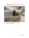
2. Place the second mounting bracket onto the top end of the Main Support. Do not
install screws into the top end bracket at this stage.
3. Place the lower end of the Main Support into the lower mounting bracket, which is
secured to the lower mounting surface.
4. Swing the Main Support into place so that it is vertical.
5. When vertical, use the supplied hardware to anchor the upper mounting bracket into
the duct ceiling.
6. Anchor the Main Support to the lower mounting bracket using two screws.
7. Anchor the Main Support to the upper mounting bracket using two screws.
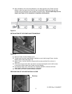
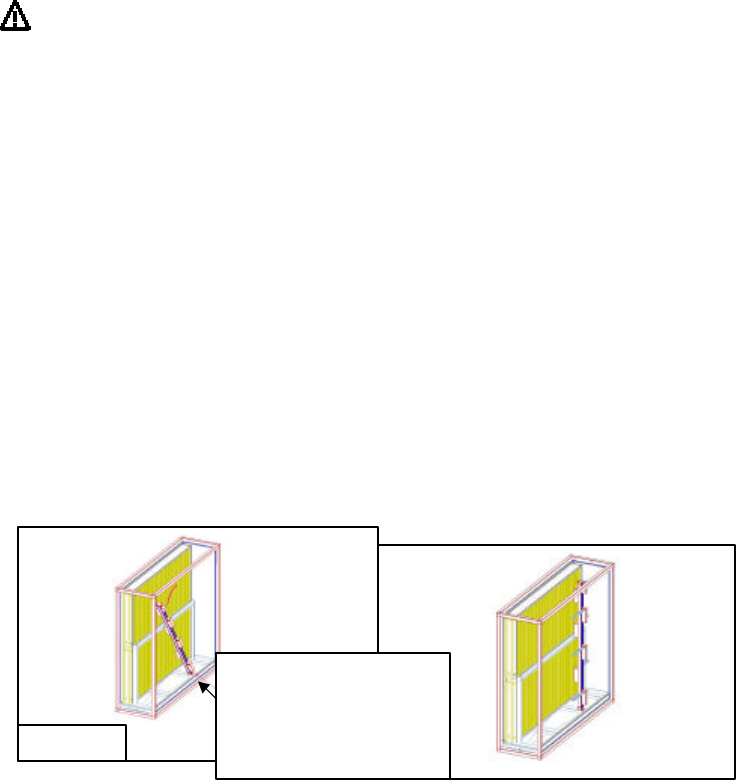
With bottom mounting bracket
screwed to extrusion and top
mounting bracket loose on extrusion
set bottom down on mounting surface
and swing up into position.
Figure 6a