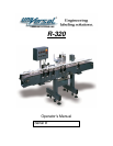
MODEL R-320
ASSEMBLY AND OPERATING INSTRUCTIONS
Conveyor Height can be adjusted from your system’s specified height by adjusting the
leveling pads
RE-TIGHTEN LOCKING BOLT AND ANGULAR BRACE, BEFORE REMOVING SUPPORT
AT BOTH ENDS OF CONVEYOR. FAILURE TO RE-TIGHTEN THE LOCKING SCREW
ON SLIDING SLEEVE COULD RESULT IN THE CONVEYOR AND ATTACHMENTS
DROPPING, CAUSING SERIOUS DAMAGE TO THE SYSTEM.
SEE APPLIER INSTRUCTION MANUAL FOR PROPER OPERATION OF APPLIER HEAD
AND WEBBING.
TO ADJUST SYSTEM FOR INDIVIDUAL CONTAINERS, PROCEED AS FOLLOWS:
1. Selecting the container to be labeled, place on conveyor for reference and adjust vertical
height of turning unit so that belt is centered vertically on container.
2. Adjust vertical height of guide rails opposite the applier and turning unit to center on product
but never low enough that rail drags on conveyor top.
3. Adjust guide rail across conveyor so that container is encapsulated securely between
the turning belt and the sponge backing plate. Move container along belt of turning
unit to establish that the sponge backing is adjusted parallel to belt. This is important,
as container must be controlled by turning unit and sponge backing on guide rail.
4. With applier head turned off, turn on conveyor. Set speed control by knob on control box on
front of conveyor to maximum speed.
5. Turn on turning unit by on-off switch located on control box on top of unit. (NOTE:
This unit’s power cord is to be plugged into control box on front of conveyor). Adjust
speed of turning unit so that turning belt is moving at a slightly higher rate of surface
speed than conveyor.
6. Place container on conveyor on entrance end and allow to proceed through turning unit.
7. When it is considered that the container is being properly controlled and guide rail
adjustments are proper, select the appropriate label; place roll on applier and web
properly. Refer to applier instructions.


