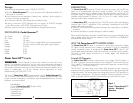
Power Force 50™ Output Waveform
The AC output waveform of the Power Force 50™ is known as a “quasi-sine wave”
or a “modified sine wave”. It is a stepped waveform that is designed to have
characteristics similar to the sine wave shape of utility power. This type of
waveform is suitable for most AC loads, including linear and switching power
supplies used in electronic equipment, transformers, and motors.
The modified sine wave produced by the Power Force 50™ inverter is designed
to have an RMS (root mean square) voltage of 110 volts, which is the same as
standard household power. Most AC voltmeters (both digital and analog) are
sensitive to the average value of the waveform rather than the RMS value. They are
calibrated for RMS voltage under the assumption that the waveform measured will
be a pure sine wave. These meters will not read the RMS voltage of a modified
sine wave correctly. They will read about 20 to 30 volts low when measuring the
output of the Power Force 50™. For accurate measurement of the output voltage
of this unit, use a true RMS reading voltmeter such as a Fluke 87, Fluke 8080A,
Beckman 4410, or Triplett 4200.
POWER SOURCE REQUIREMENTS
The Pocket Generator™ battery must provide between 10.5 and 14.5 volts DC
and must be able to supply the necessary current to operate the load. To obtain a
rough estimate of the current (in amperes) the power source must deliver, simply
divide the power consumption of the load (in watts) by 10.
Example: If a load is rated at 50 watts, the power source must be able to deliver:
50 ÷ 10 = 5 amperes
Connection To Load
Connect the Pocket Generator™ to the vehicle’s cigarette lighter socket using the
cigarette lighter plug provided. The Power Force 50™ is equipped with a standard
AC household-type receptacle. Plug the cord from the equipment to be operated
into the AC receptacle. The green LED indicator will illuminate to indicate that the
unit is functioning. Make sure the load requirements of your equipment are within
the parameters of the Power Force 50™ output. If so, turn on the equipment.
9
Figure 2: Power Force 50
™
- Modified Sine Wave
1
2
3
4
6
To Use The Pocket Generator™ To Boost Vehicle’s
Low Battery System
WARNING: Be sure that the ON/OFF switch on the inverter is in the OFF
position, before using unit as Battery Booster. Failure to do so may cause damage
to the inverter, and will void manufacturer’s warranty. NOTE: The Pocket Generator™
will not fully charge a completely dead battery, but it can be used to boost a
vehicle’s weak battery system, or to provide auxiliary power for the onboard
electrical systems and selected memory settings for electronics (A/C, seats, radio,
etc.). Using the adapter cord with two cigarette lighter-type plugs, insert one end
of the cord into the vehicle’s cigarette lighter receptacle, and the other end into the
corresponding receptacle on the Pocket Generator™. When power assist is
completed, disconnect the adapter cord’s plugs from the vehicle’s cigarette lighter
receptacle and the Pocket Generator™.
To Use The Pocket Generator™ As A Memory Saver For
Onboard Systems And Pre-Sets
WARNING: Be sure that the ON/OFF switch on the inverter is in the OFF
position, before using unit as Memory Saver. Failure to do so may cause damage
to the inverter, and will void manufacturer’s warranty. When the vehicle’s battery
system is to be disconnected for repair or maintenance, the Pocket Generator™
will provide auxiliary power to maintain the selected memory settings and other
onboard electrical systems, until power is restored. BEFORE the vehicle’s battery
system is disconnected: using the adapter cord with two cigarette lighter-type plugs,
insert one end of the cord into the vehicle’s cigarette lighter receptacle, and the
other end into the corresponding receptacle on the Pocket Generator™. Onboard
power will be maintained. AFTER the vehicle’s battery system is reconnected,
disconnect the adapter cord’s plugs from the vehicle’s cigarette lighter receptacle
and the Pocket Generator™.
Fuse Replacement
Main Fuse
1. Open the top flap of the Pocket Generator™,
carrying case. The main fuse holder’s
screw-on/off cap will immediately be visible.
2. Unscrew the fuse holder cap and remove the fuse.
3. Replace with a new 10 amp fuse, if needed.
4. Screw fuse holder cap back on.
5. Close case securely.
Fig. B.


