TERMINAL SETUP AND USAGE
RS-232 and USB Connections
V
X
700 INSTALLATION GUIDE 25
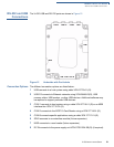
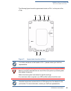
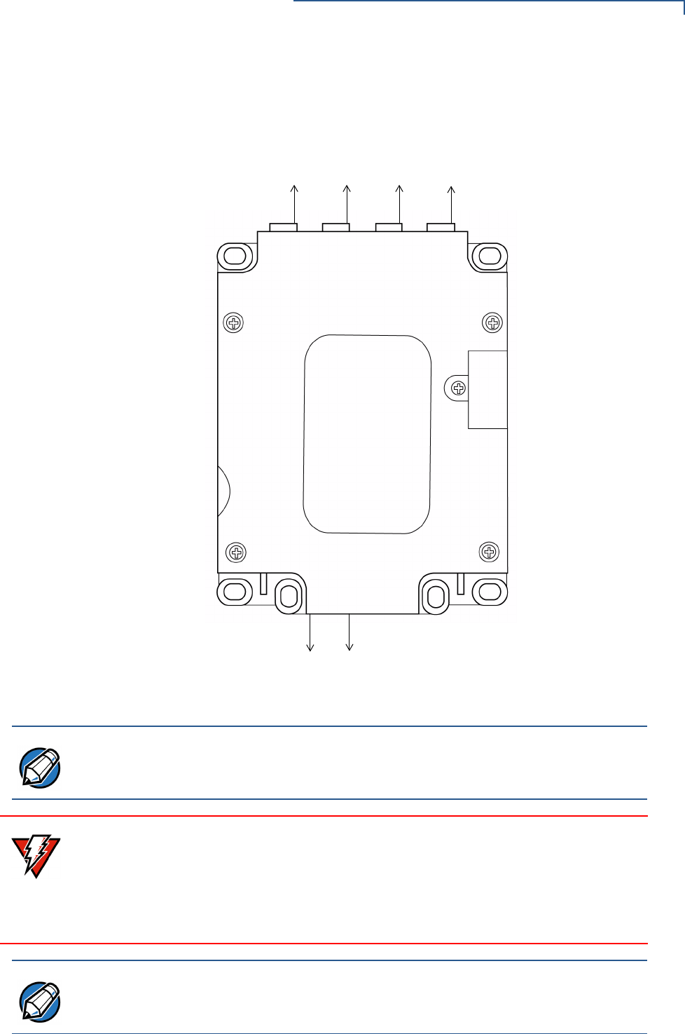
The following figure shows the approximate location of Pin 1 on the ports of the
V
x
700:
Figure 13 Approximate Location of Pin 1
COM 2 USB 2/3 COM 8 MSR
SAM
SDIO
USB
COM1 DCIN
PIN 1 PIN 1
PIN 1
PIN 1
PIN 1 PIN 1
NOTE
For further assistance on the location of Pin 1, please contact your VeriFone
representative.
WARNING
Turn off or unplug the host system when connecting or disconnecting the V
x
700.
Memory corruption and data loss can result if the host system is processing data
when power is removed.
Refer to the host system instructions for specific warnings.
If an extension cable is required, only USB-certified cables should be used.
NOTE
Standard accessories included with the V
x
700 depends on the selected V
x
700
part number. For more information, contact your VeriFone representative.


