


8 VS375C/VS575C
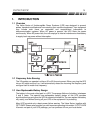
AC Mode
When this Green LED is lit, the UPS is in normal mode,
and providing power to your equipment. The UPS will
continue to filter and provide surge protection.
Battery Mode
When this Yellow LED is lit, the UPS is providing power
from its battery. Also, this LED is lit when you press the
button to test the battery.
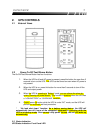
Battery Fault
This Red LED indicator indicates two statuses of the UPS:
When this Red LED is on, it indicates that the battery
needs to be replaced. When this Red LED is flashing
rapidly, it indicates the UPS is over
loaded.
2.4 Communication Port (Remote Port)
This port allows for a computer to monitor the status and control the operation of the UPS.
Its functions include the following:
♦ To broadcast a warning when power fails.
♦ To close any open files before the battery reserves are exhausted.
♦ To turn off the UPS.
*Note that software and the communication cable are only available in certain areas.
Contact your local dealer for more information.
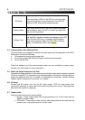
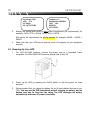
2.5 Data Line Surge Protection (In & Out)
The data line surge protection on the rear panel provides an easy way to protect a network
(RJ45) or modem(RJ11) connection from hazardous spikes. Connect a network cable or a
single line telephone into the “In” socket. To complete the connection, connect another
network cable or telephone line into the “Out” socket.
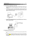
2.6 AC Input
Connect the AC power cord into the AC Input socket. UPS can have power from
commercial electricity. It has a fuse in the socket to protect over current. The spare fuse
also inside the socket for replacing.
2.7 Output outlet
There are two kinds function output outlets:
1. Bypass : These output outlets offer surge protection only. It won’t have back up
power at inverter mode.
2. UPS outlet : These output outlets not only offer surge protection but also back up
power to your main equipments at inverter mode.