


(2) Batteries, AAA
(1) VL8000 Installation Manual
(1) VL8000 Owner’s Manual
VL8000 Kit contents:
(1) Visor with Monitor and Cable
(1) A/V Module
(1) 12V Harness for A/V Module
(1) Remote Control
12V Power Installation
We recommend the installation of a main power switch for the entire headrest system.
The circuit should be marked to assist the consumer in locating the correct vehicle fuse
for the video system in the case of a system failure.
AV Module Installation
1. Place A/V module in a well protected area under a seat or behind a panel.
2. Connect the 12V harness to the same 12V+ and 12V Ground as the Video Source Unit(s).
3. Insert 12V harness connector into A/V module.
4. Insert video cable from Source.
5. Insert video output cable connecting the Headrest.
6. Install I/R extender cable from source unit to A/V module.
System Operation
Please see CONTROLS on page 4, 5 and 6 of the VL8000 Owner’s Manual for system
operation instructions.
Sp ecifications
ELECTRICAL SPECIFICATIONS – 7.0”
Display Type: LCD
Screen size: 7.0” (Diagonal)
Resolution: 1,440 (W) x 234 (H)
Number of Pixels: 336,960
Brightness: 400 nit
Horizontal view angle: ±65°
Vertical view angle: +40°, -65°
Power requirement: (Monitor) DC 12.0V ±1.5
Power consumption: (Monitor) DC <1A
Note: Designs and specifications are subject to change without notice and without
legal obligation.
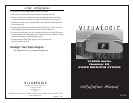
Visor Removal Instructions
1. Use a small blade screwdriver
to insert in access slot to
depress the retaining tab.
2. With the screwdriver in the
slot, push the elbow of the
visor up, towards the roof.
3. Pushing up on the visor will
release it form the roof header.
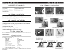
4. Locked Position (installed) 5. Service Position (ready to un-install)
Lock Position Service Position
6. With the visor now in service
position, pull the visor bracket
down. This will remove the
visor completely from the
roof header and headliner.
7. Disconnect lighted
mirror wires.
8. Remove shipping ring by
disengaging all 3 locking tabs
and do not re-install.
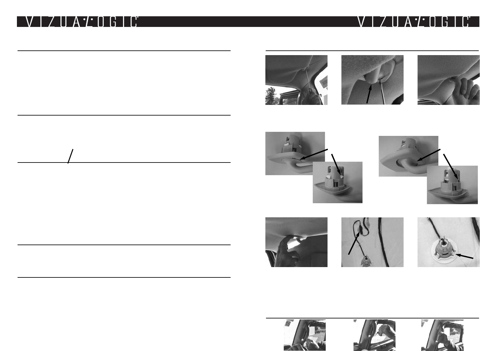
A-PillAr Trim removAl tip
1. Remove the upper retaining clip from
passenger-side A-pillar assist handle
2. Remove the lower retaining clip from
passenger-side A-pillar assist handle
3. Remove passenger-side A-pillar assist
handle by pulling straight away from the
A-pillar. Remove passenger-side A-pillar
trim by pulling at edge of panel.