


Specifications
Operator Interface
• 32-character vacuum florescent display
• 8-key keypad to access guided menus and prompts,
set values and view channel displays
• Built-in context sensitive help
Noise Rejection
• 120dB at 60Hz
Temperature Coefficient
• 40ppm/°C
Analog Inputs
• Thermocouples: user selectable type, direct connection,
linearization, reference junction compensation, reversed
and shorted thermocouple detection and upscale break
protection with output averaging.
• RTD: 2-or 3-wire, platinum, 100Ω @ 0°C, DIN curve.
Requires scaling resistors. See special inputs in ordering
information.
• Linear: current and voltage signals from linear transmitter
Input Range and Accuracy
Sensor Range (°C) Range (°F) Accuracy
Type B 66 to 1760°C 150 to 3200°F ±4.0°C
Type E -200 to 787°C -328 to 1448°F ±1.0°C
Type J -212 to 760°C -350 to 1400°F ±1.2°C
Type K -268 to 1371°C -450 to 2500°F ±1.3°C
Type R -18 to 1766°C 0 to 3210°F ±2.8°C
Type S -18 to 1760°C 0 to 3200°F ±2.8°C
Type T -268 to 399°C -450 to 750°F ±1.6°C
RTD -200.0 to 621.1°C -328.0 to 1150.0°F ±0.5°C
Note: Accuracy @ 25°C (77°F) ambient. Valid for 10 to 100
percent of span except Type B, which is specified for
427°C (800˚F) to 1760˚C (3200˚F). RTD is for 100 per-
cent of span.
Linear Voltage and Current Inputs
Requires scaling resistors. See special inputs in ordering
information.
0-10mAÎ(dc)
0-20mAÎ(dc)/4-20mAÎ(dc)
0-100mVÎ(dc)
0-500mVÎ(dc)
0-1VÎ(dc)
0-5VÎ(dc)
0-10VÎ(dc)
0-12VÎ(dc)
Other ranges available. Consult factory.
Input Sampling Rate at 60Hz
Each channel has the following scans per second:
• D84: 6 samples per second, (update time: 0.167 sec.)
• D88: 3 samples per second, (update time: 0.333 sec.)
Internal Measurement Resolution
• 0.006 percent, greater than 14 bits
Calibration
• Automatic zero and full scale
Digital Inputs
• TTL level used for logic, remote alarm acknowledge,
selecting recipes or jobs
• 8 inputs with 50-pin terminal board option
• 3 inputs with 18-pin terminal block option
Digital Outputs
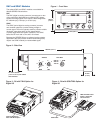
• 18 digital outputs are available with a 50-pin terminal
board option (See Figure 4 on previous page)
• 11 outputs available with 18-pin terminal block option
(See Figure 3 on previous page)
• 1 or 2 control outputs are user assigned for each loop
• Each control output can be configured for on-off, time
proportioning or distributed zero crossing
• Outputs sink up to 60mA each at 5VÎ(dc)
• 350mA at 5VÎ(dc) available from onboard supply
Alarm Outputs
• Independent process and deviation alarms for each
channel
• Alarms can operate any output not used for control
• User programmable deadband, delay and startup
suppression
• Global alarm output activates when any alarm occurs
• Watchdog output indicates controller is functioning correctly
DeviceNet™ Interface
• Fully compliant with the interface guidelines for DeviceNet™
on semiconductor manufacturing tools
• Supports predefined master/slave connection set
• Group two only slave device
• Module status and network status LEDs
• Rotary baud rate and node address switches
• Hardware and software selectable baud rates: 125K, 250K
and 500K
• Hardware and software selectable node address: 0 to 63
• Supports polled I/O and explicit messaging connections
• Polled I/O response: less than 1 millisecond
• Explicit message response: less than 50 milliseconds
• EDS (Electronic Data Sheet)
• Connector: 5-pin, micro style, sealed, male
• Optically isolated CANBUS interface
• Bus plug-able while hot
• Bus mis-wire protection
Line Voltage/Power
• 15 to 24 ± 3VÎ(dc) @ 1A (loaded) or 300mA (no load)
Agency Approvals
•UL
®
, C-UL
®
listed: UL
®
61010-1 safety requirements for
measurement, control and laboratory equipment
• CE Mark: See Declaration of Conformity for details
• ODVA conformance tested DeviceNet™