


2-6
Unit Description
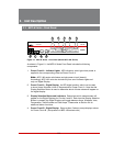
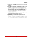
5. Network Port: An RJ45 Ethernet port for connection to your 100Base-T, TCP/IP
network. Note that the MPC features a default IP address (192.168.168.168). This
allows you to connect to the unit without first assigning an IP address. Note that the
Network Port also includes two, small LED indicators for Link and Data Activity. For
more information on Network Port configuration, please refer to Section 5.9.
6. Console Port: A DB9, RS232 serial port (DTE), which can be used for connection
to a local terminal or external modem, as described in Section 4. For a description
of the Console Port interface, please refer to Appendix B.1.
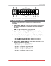
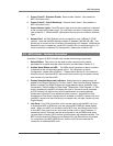
7. Power Circuit A - Digital Display: An LED digital readout, which can be used
to show Amps, Kilowatts, Volts or Temperature for Power Circuit A. Note that the
Display Selection Button (Item 3) is used to determine which of these values will
appear on the digital display.
Note: Some MPC models include only one power circuit. Accordingly, MPC
models that include only one power circuit, the unit will also have only one
digital display.
8. Power Circuit B - Digital Display: Same as Item 7 above, except displays values
for Power Circuit B. MPC Models that include only one power circuit will also have
only one digital display.
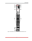
9. Power Circuit A - Switched Outlets and Indicator Lights: AC Outlets that can be
switched On, Off or rebooted in response to user commands. Note that each outlet
includes an LED Indicator, which lights when power is applied to the outlet.
Notes:
• Some MPC models include only one power circuit.
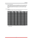
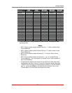
• Please refer to the table in Section 1 or Section 3 for power ratings for your
specific MPC model.
10. Power Circuit B - Switched Outlets and Indicator Lights: Same as Item 9 above,
except outlets and LED indicators are for Power Circuit B. Note that some MPC
models include only one power circuit.
11. Circuit Breaker(s): Some MPC models include two power circuits, with two
breakers for each circuit, and other MPC models include only one power circuit with
two circuit breakers. For a description of the power rating for your specific MPC
model, please refer to the table in Section 1 or Section 3.
12. Unit Bottom Plate: In all models except MPC-20V-1 and MPC-20V-2, the power
inlets are located on the bottom plate of the unit. In MPC-20V-1 and MPC-20V-2
models, the power inlets are located at the bottom of the front panel.