


Page 3
1. Introduction
This Quick Start Guide describes the installation procedure for the PTS series
hardware. The PTS is essentially a power fallback switch, that automatically
switches power from a primary input to a secondary input when power to the
primary input is lost or interrupted.
2. Hardware Installation
Apply Power to the MPC
Refer to the warnings and cautions at the beginning of this guide and the
power rating nameplate on the PTS back panel, and then connect the unit to
two appropriate power sources. For units with detachable power input cables,
connect the power input cables to the power inlets, install the cable keepers, and
then connect the primary power input cable to your primary power supply and
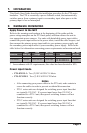
the secondary power input cable to your secondary power supply. Refer to the
table below for information concerning power requirements and maximum loads.
Model No.
Input
Feeds (x2)
Input
Voltage
Max. Load
per Outlet
Outlets
Max. Load
per Unit
PTS-8NE15-1 15 Amps 100 to 120 VAC 12 Amps 8 ea. NEMA 5-15R 12 Amps*
PTS-9CM20-2 20 Amps 200 to 240 VAC 10/16 Amps 8 ea. IEC-60320-C13
1 ea. IEC-60320-C19
16 Amps*
* In accordance with UL requirements, this value has been de-rated to 80%.
Power Input Feeds:
• PTS-8NE15-1: Two (2) IEC-60320-C14 Inlets.
• PTS-9CM20-2: Two (2) IEC-60320-C20 Inlets.
Notes:
• After connecting your power cables to the PTS unit, make certain to
secure the cables in order to prevent accidental disconnection.
• PTS-1 series units are designed for switching power input lines that
are typically 120 VAC. If a power input lower than 120 VAC is
connected to a PTS-1 unit, then power switching features will not
function correctly.
• PTS-2 series units are designed for switching power input lines that
are typically 240 VAC. If a power input lower than 240 VAC is
connected to a PTS-2 unit, then power switching features will not
function correctly.