OPERATING PRINCIPALS
23
22
OPERATION
Some Powerful Advice.
Your Whistler i n v e rter will work best when placed on a re a-
sonably flat surface. The floor or wall of your vehicle are good
l o c a t i o n s .
When driving with the inverter in operation, make certain that
neither the inverter nor the power cords will impede safe
operation of your vehicle. Keep the unit and all cords clear of
the steering wheel, gas, brake and clutch pedals and gear
s h i f t .
To maintain your inverter in proper working condition,
note the following important safety pre c a u t i o n s :
• MOISTURE. Keep the inverter dry. Do not expose it
to m o i s t u r e. Do not operate the inverter if you, the
i n v e rt e r, the device being operated or any other sur-
faces that may come in contact with any power
sources are wet. Water and many other liquids can
conduct electricity which may lead to serious injury or
death.
• HEAT. For peak efficiency, the ambient air tempera-
ture should be between 50° and 80° F. Avoid placing
the i n v e rter on or near heating vents, radiators or
other sources of heat. Do not place the inverter in
d i rect sunlight.
• V E N T I L ATION. In order to disperse the heat generat-
e d while the inverter is in operation, keep it well venti-
lated. While in use, maintain several inches of clear-
ance around the top and sides of the inverter.
• FUMES & GASES. Avoid using the inverter near
flammable materials. Do not place the inverter in
areas such as battery compartments, where fumes or
gases may accumulate.
For You Technical Types.
1. Basic Operating Principles:
Whistler i n v e rters work in two stages. During the first stage,
the DC to DC converter increases the DC input voltage fro m
the power source (e.g. a 12 volt battery) to 145 volts DC. In
the second stage, the high voltage DC is converted to 110
volts (60 Hz AC) using advanced power MOSFET transistors
in a full bridge configuration. The result is excellent overload
capability and the capacity to operate difficult reactive loads.
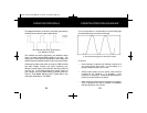
The output waveform resulting from these conversions is a
"quasi-sine wave" or a "modified sine wave" as shown on the
following page.
1250/1750/2750 Manual 3/6/02 2:45 PM Page 25


