


Two Channel Infrared Modulator
• Model MOD 232
Two Channel Infrared Modulator
• Model MOD 232
©2007, Williams Sound Corp. MCAT
002B 1
NOTE: SPECIFICATIONS SUBJECT TO CHANGE WITHOUT NOTICE!
D
D
Description:
The MOD 232 Modulator is designed to operate with a TX9 emitter operating on 2.3/2.8/3.3/3.8 MHz
frequency. Each microprocessor controlled MOD 232 modulator can handle up to two audio channels.
Baseband outputs can daisy-chain two MOD 232 together for four-channel operation. Flexible combi-
nation jacks permit balanced/unbalanced line-level inputs. Carrier frequencies are controlled by the
microprocessor and a frequency synthesizer for rock-solid frequency control.
Applications:
• Churches • Schools • Auditoriums • Conference Rooms • Theaters
Size, Weight: 8.5" W x 8.2" D x 1.7" H (21.5 cm x 20.8 cm x 4.4 cm), 3.1 lbs (1.5 kg)
Color: Black epoxy paint with white legends
Rack Mount: 1/2 rack space wide, 1 rack space high, one or two modulators may be mounted in a
single IEC rack space with RPK 005 (single) or RPK 006 (double) Rack Mount Kits
Power Supply: Wall Transformer, 24 VAC, 50-60 Hz, 15VA
North America: TFP 016, UL/CSA
Europe: TFP 027-01, 2-pin Schuko plug, CE
UK: TFP 027-02, 3-pin UK plug, CE
Modulation: FM Wideband, +50 kHz deviation, 50 uS pre-emphasis
Carrier Frequency: Channel A: Selectable, 2.3/2.8/3.3/3.8 MHz,
Channel B: Selectable, 2.3/2.8/3.3/3.8 MHz
Signal-to-Noise Ratio: More than 60dB
Frequency Response: 30 to 16,000 Hz, +1 dB, -3 dB, electrical response
Total Harmonic Distortion: Less than 2%, electrical response
Audio Processing: Compression (slope) adjustable from 1:1 to 4:1
Switchable compression gain: Moderate: 16dB. Max: 33dB
Auto Carrier Shut-Off: 15-minute timer shuts off carrier when no audio is present (can be disabled)
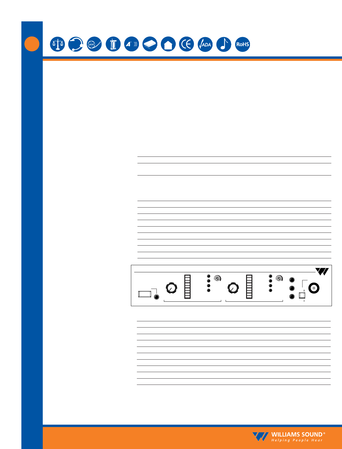
Power Switch: Two-position push button, ON/OFF
Power Indicator: Green LED
Audio Level Controls: CHA and CHB Input Level, rotary knobs
Audio Indicators: CHA and CHB Audio Level, 10-segment LED’s
Carrier LEDs: 4 green LED carrier “on” indicators per channel (indicates frequency, malfunctions)
Compress Control: 1:1 to 4:1
Input Mix LED: Indicates inputs A and B audio are mixed and transmitted by CHA and CHB off
Stereo LED: Indicates stereo mode
Phones Switch: Selects CH1 or CH2 for phones when not in stereo mode
Phones Output: 1/4" TRS headphone jack. Accepts stereo, mono and any impedance phones.
Infrared Test LED: IR LED for receiver testing, monitoring and audio signal testing.
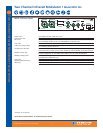
MOD 232 Modulator:
MOD 232 Front Panel:
Two Channel Infrared System Modulator
Williams Sound
Power
Phones
+9
+6
+3
0
-3
-6
-9
-12
-15
-18
+9
+6
+3
0
-3
-6
-9
-12
-15
-18
3.8
3.3
2.8
2.3
Level
5
0
1
2
3
46
7
8
9
10
Level
5
0
1
2
3
46
7
8
9
10
Compress
3.8
3.3
2.8
2.3
Compress
Inputs Mixed
Stereo
IR
CH A
CH B
Frequency
(MHz)
Frequency
(MHz)
Channel A Channel B
Microprocessor Controlled
Frequency Synthesized