


Two Channel Infrared Modulator
• Model MOD 232
Two Channel Infrared Modulator
• Model MOD 232
©2007, Williams Sound Corp. MCAT
002B 2
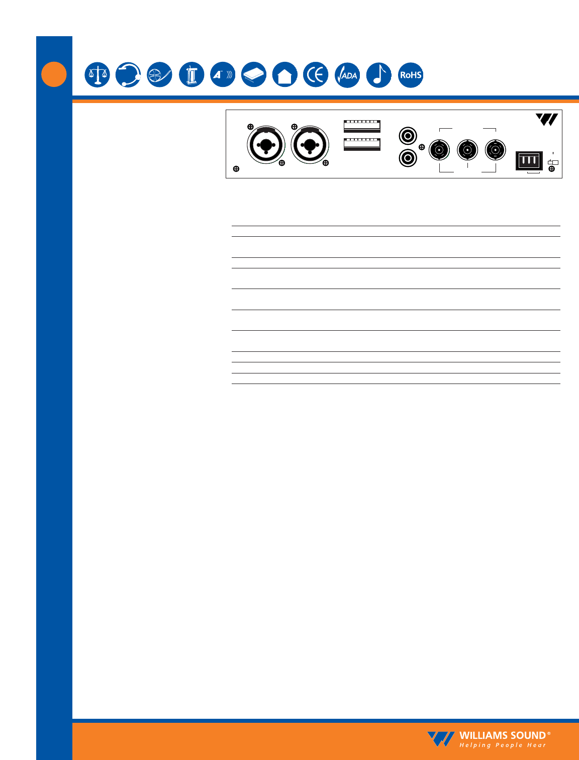
Power Input: 3-Pin Molex, 24 VAC, 50-60 Hz, 15 VA
Audio Input Jack: CHA and CHB combination XLR/TRS jack
Mic Level: Balanced, Lo-Z, 100 µV min. to 90 mV max., 1 mV nominal, 3kΩ input impedance, sup-
plies switchable simplex power per DIN 45596 for condenser mics
Line Level: Balanced or unbalanced, 21 mV min. to 10V max., 212 mV nominal, 100 kΩ
Audio Line Output Jacks: RCA Jack, CHA and CHB, 500 mV, unbalanced, 100 Ω source impedance, load imped-
ance must be greater than1 kΩ
Configuration Switches: CHA and CHB 8-position DIP switch, selects Mic/Line input, compressor gain, simplex
power, discrete or mixed inputs, carrier frequency, channel disable, auto shut-off timer
Baseband Input Jack: BNC, allows mixing with additional MOD 232 Modulator (4CH operation), 100 mV, 50
Ω input impedance, use with MOD 232 or MOD 112 (111), BNC, RG-58 Cable
Baseband Output Jack: Two BNC jacks carry baseband signal, 100 mV/channel, 50 Ω source impedance, for use
with WIR TX9 or MOD 232 only
Approvals: CE, FCC, RoHS, WEEE
Operating Requirements: 0-50º C ambient temperature, non-condensing, non-corrosive atmosphere
Warranty: 5 years on modulator*
NOTE: SPECIFICATIONS SUBJECT TO CHANGE WITHOUT NOTICE!
D
D
Configuration
Switches
Input CH A Input CH B
Audio Line
Output
CH A
CH A
CH B
CH B
50 Ohms
100 Ohms
Made in USA
24V
24 VAC, 15 VA, 50-60 Hz
Power In
Baseband
Input Output Output
MOD 232 Infrared System Modulator
Plug
Williams Sound
12345678
12345678
MOD 232 Rear Panel:
*90 days on accessories.