


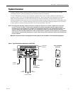
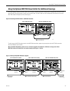

Connect Audio Source
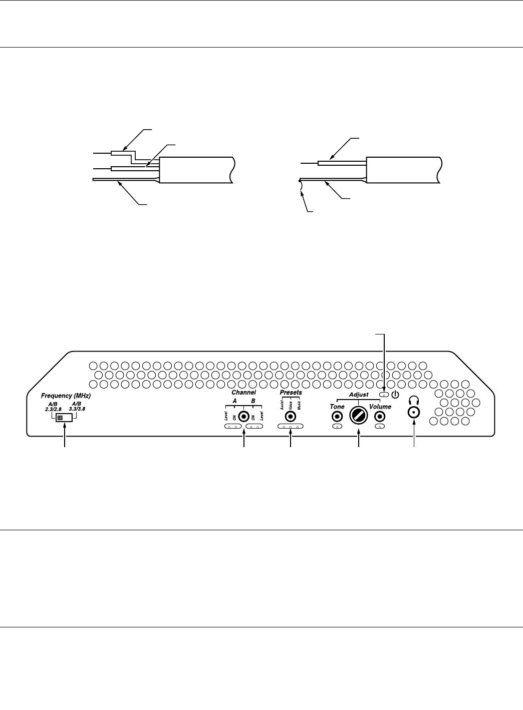
Determine the length of the audio cable needed to connect to the sound system to the WIR TX90 transmitter. Install the supplied
Phoenix connector on the end of the audio cable to be connected to the transmitter. See the back of the WIR TX90 for wiring
instructions.
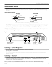
LINE LEVEL BALANCED OR UNBALANCED (5V P/P MAXIMUM AUDIO)
A232
BALANCED UNBALANCED
SIGNAL
SHIELD
–
G
+
SIGNAL
SHIELD
–
G
+
SIGNAL
JUMPER
Figure 8: Audio Source Connections
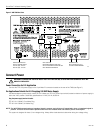
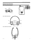
A231
POWER ON INDICATOR
FREQUENCY
SELECTION CONTROL
(2.3/2.8 OR 3.3/3.8)
CHANNEL
ON/OFF
CONTROL
CHANNEL
ON/OFF
CONTROL
AUDIO
ADJUSTMENT
CONTROL
(VOLUME/TONE)
AUDIO
ADJUSTMENT
CONTROL
The WIR TX90 will accept line level, balanced or unbalanced audio inputs. If you wish to operate in single channel mode, plug the
audio cable with the installed Phoenix connector in “Channel A” OR the “Channel B” connector. If you choose to operate in two
channel mode, plug the audio cables with Phoenix connectors in both “Channel A” AND “Channel B” connector.
NOTE: By default, the WIR TX90 is set to operate in two-channel mode. To turn Channel A or Channel B on/off, refer to the
instructions Selecting a Channel, below.
Selecting a Carrier Frequency
The WIR TX90 offers two sets of carrier frequencies for Channel A and Channel B:
2.3 and 2.8MHz or 3.3 and 3.8MHz.
The WIR TX90 is preset to 2.3 and 2.8 MHz, which are the most commonly used. Move the slide switch to select a pair of
operating frequencies.
Selecting a Channel
To activate a channel, press the “CHANNEL” button until the channel “ON” indicator lights. For example, to operate only channel
A, press the “CHANNEL” button until only the channel A “ON” indicator lights. To operate both channel A and B, press the
“CHANNEL” button until both “ON” indicators light.
Note: If you’re only using one channel, make sure the other channel is turned off to maximize system coverage.
Figure 9
7
SoundPlus
™
Infrared Listening System
MAN 119H