Series or Parallel Connection with Other Outputs
The outputs of the power supply are fully floating and may be used in series with other power
supply units to generate high DC voltages up to 300V DC.
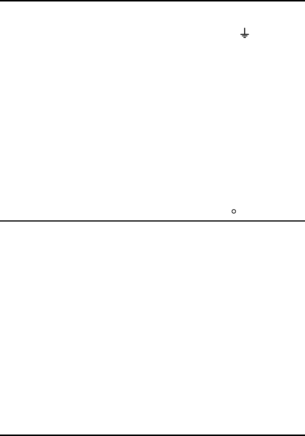
The maximum permissible voltage between any terminal and earth ground (
) is 300VDC.
WARNING! Such voltages are exceedingly hazardous and great care should be taken to shield
the output terminals for such use. On no account should the output terminals be touched when
the unit is switched on under such use. All connections to the terminals must be made with the
power switched off on all units.
It should be noted that the unit can only source current and cannot sink it, thus units cannot be
series connected in anti-phase.
The unit can be connected in parallel with others to produce higher currents. Where several units
are connected in parallel, the output voltage will be equal to that of the unit with the highest
output voltage setting until the current drawn exceeds its current limit setting, upon which the
output will fall to that of the next highest setting, and so on. In constant current mode, units can
be connected in parallel to provide a current equal to the sum of the current limit settings.
Note that the output terminals are rated at 15A maximum; if several outputs are operated in
parallel to source higher currents than this the junction should be made at a separate point, not
one of the terminals.
Over-temperature Protection
Sensors on both the primary and secondary heatsinks will detect over-temperature due to
blocked air flow, fan failure or other circuit fault. Over-temperature will shut down the output (the
display will read 0 Volts and 0 Amps if the output is ON) though the output ON lamp will remain lit.
The output will remain shut down even after the heatsinks have cooled down. When the cause of
the over-temperature has been removed and the heatsinks have cooled to normal working
temperatures the output can be reset by turning the POWER switch off (
) then on (
l
) again.
Maintenance
The Manufacturers or their agents overseas will provide repair for any unit developing a fault.
Where owner wish to undertake their own maintenance work, this should only be done by skilled
personnel in conjunction with the service manual which may be purchased directly from the
Manufacturers or their agents overseas.
Fuse
The correct fuse type is:
10 Amp 250V HBC time-lag(T), 5 x 20mm.
Note that the main function of the fuse is to make the instrument safe and limit damage in the
event of failure of one of the switching devices. If a fuse fails it is therefore very likely that the
replacement will also blow, because the supply has developed a fault; in such circumstances the
instrument will need to be returned to the manufacturer for service.
Make sure that only fuses of the required rated current and specified type are used for
replacement. The use of makeshift fuses and the short-circuiting of fuse-holders is prohibited.
To replace a fuse, first disconnect the instrument from the AC supply. Remove the 6 cover
securing screws and lift off the cover. Replace the fuse with one of the correct type and refit the
cover.
Cleaning
If the PSU requires cleaning use a cloth that is only lightly dampened with water or a mild
detergent. Polish the display window with a soft dry cloth.
WARNING! TO AVOID ELECTRIC SHOCK, OR DAMAGE TO THE PSU, NEVER ALLOW
WATER TO GET INSIDE THE CASE. TO AVOID DAMAGE TO THE CASE OR DISPLAY
WINDOW NEVER CLEAN WITH SOLVENTS.
8


