


Installation and Configuration
Configure for Multichannel Operation
36 Operating Manual for Multichannel Functionality (GPIB-M)
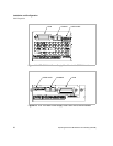
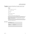
CANbus The CANbus port consists of two 4-pin modular “handset” jacks to support daisy
chain connections. The CAN (Controller Area Network) is an ISO standard
(ISO11898) for a serial communication network. Table 2.2 describes the pin
functions. The CANbus is used for communications in multichannel operation or
current sharing (master/slave) operation.
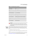
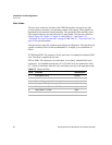
Table 2.2 CANbus Pins
CANbus
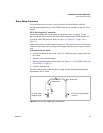
Cables
The custom CANbus cables shipped with your unit are parallel 4-connector cables
with 4-pin modular “handset” connectors.
Configuration
of CAN-only
Interface
Cards
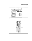
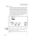
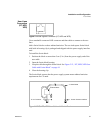
The CAN-only interface cards must be configured via the CANbus with another
GPIB-M card. The CAN-only interface cards are set to multichannel address 2 at the
factory. Ensure the multichannel address on the GPIB-M is set to an unused address,
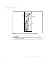
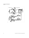
for example, address 1. Connect the two power supplies as shown in Figure 2.10,
“Connections for Multichannel Operation” on page 37.
Send the query to the CAN-only power supply:
SYST2:REM:SOUR?
and ensure the response is “MCH” for multichannel.
If necessary, set the power supply to accept control via multichannel commands
(the CANbus interface) with the SCPI command:
SYST2:REM:SOUR MCH
Set each slave's unique multichannel address using the command:
SYST2:COMM:MCH:ADDR <multichannel-address>
where multichannel-address is an integer in the range of 1-50.
This procedure can be repeated separately with each power supply to assign a unique
address to each. Once all power supplies are configured, they can be connected to the
CANbus network.
Pin # Function
1CANLO
2 Ground
3CANHI
4 Ground
Note See “Broadcasting Commands” on page 39 for additional information on
configuring CAN-only units.